Camera supplementary lighting device and control method thereof

A technology for cameras and camera components, applied in the field of cameras, can solve problems such as affecting the appearance, excessive light supplement, and increasing costs, and achieve the effects of simple and reasonable structure, high control precision, and improved consistency

Inactive Publication Date: 2012-07-18
MIDEA GRP CO LTD
View PDF8 Cites 23 Cited by
  • Summary
  • Abstract
  • Description
  • Claims
  • Application Information

AI Technical Summary

Problems solved by technology

[0002] The home appliances with video monitoring function in the prior art generally ensure the light transmission effect of the camera supplementary light, and the light transmission area is transparent, so that the internal circuit board and other internal components can be seen from the outside, which is very convenient. It is not beautiful, which is undoubtedly a major shortcoming in the field of home appliances that emphasize appearance
There is only one set of control at the same time. When filling the light, the fill light is either all on or off; sometimes there will be an embarrassing situation where the fill light is too much when all are turned on, and the intensity of the light is not enough when it is turned off.
The use of photoresistors in brightness detection will not only increase the cost, but also affect the appearance, because the photoresistor needs to transmit light, and the appearance is ugly, and the consistency of the photoresistor is also poor.

Method used


Image

  • Camera supplementary lighting device and control method thereof
  • Camera supplementary lighting device and control method thereof
  • Camera supplementary lighting device and control method thereof

Examples


no. 1 example

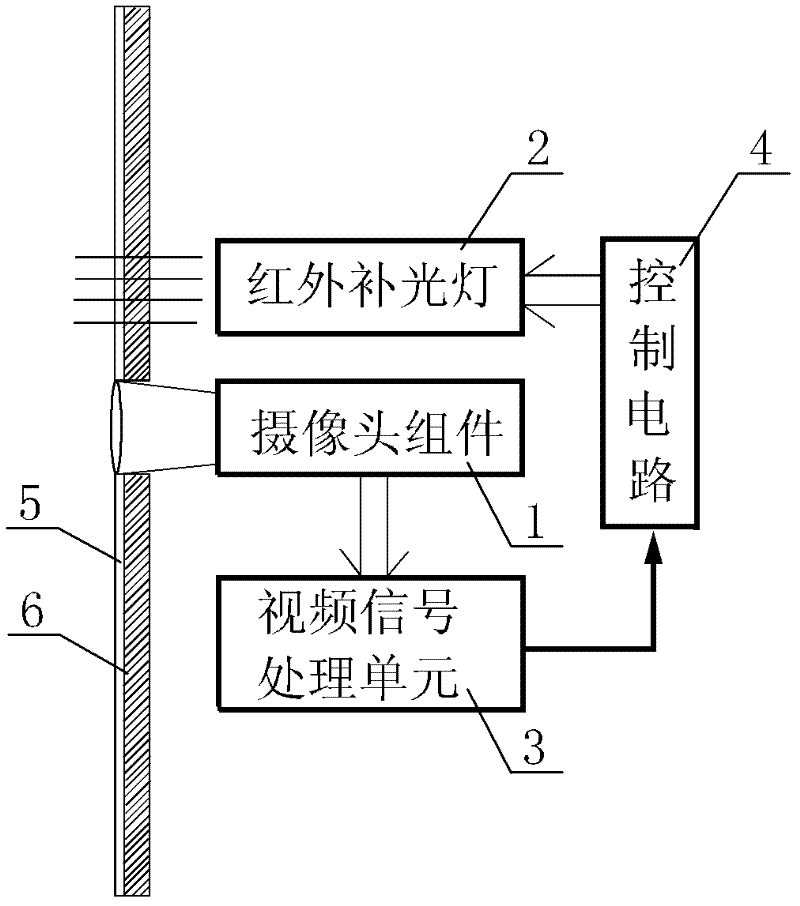
[0022] see Figure 1-Figure 3 , the camera supplementary light device is suitable for security cameras of household air conditioners, including a camera assembly 1 and a video signal processing unit 3 arranged in the main body of the device. . The light-transmitting plate 6 is transparent glass, and the light-transmitting plate 6 is provided with a special paint coating 5 that absorbs visible light. The paint coated on the special paint coating 5 uses IR ink, which is generally referred to as an infrared-transmitting ink. The infrared rays of the fill light 2 can penetrate the special paint coating 5, but the special paint coating 5 cannot block the light of the lens on the camera assembly.

[0023] The paint applied to special paint coating 5 has a special effect: it can let infrared light pass through the coating, but visible light cannot pass through. The working principle is that the coating adds a special substance, the The material is sensitive to the wavelength of the...

no. 2 example

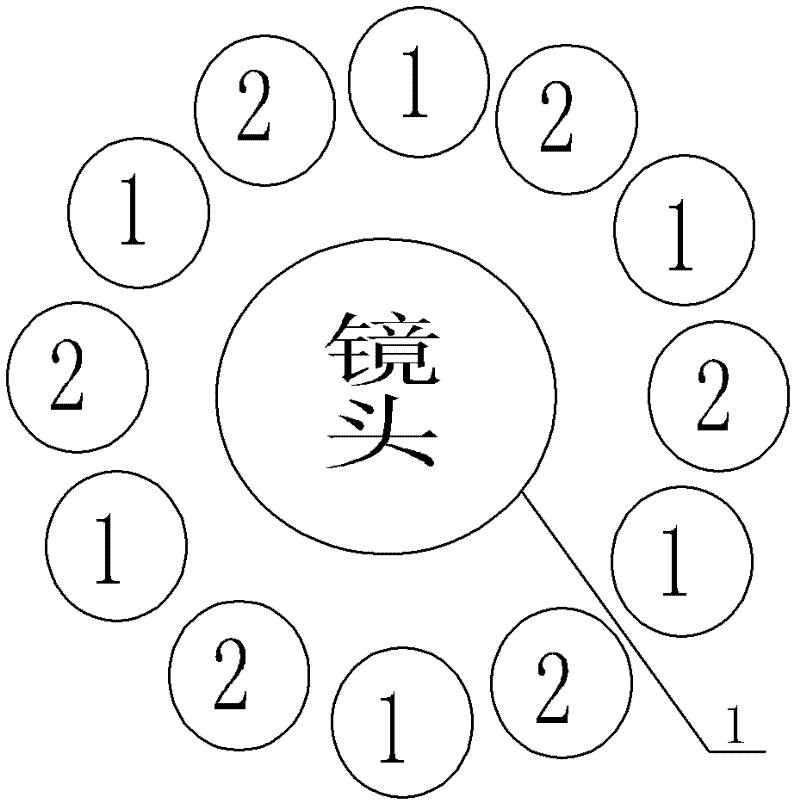
[0033] see Figure 4 , the infrared supplementary light lamp 2 is in a linear array, and the infrared supplementary light lamp 2 includes three groups of LED lamps arranged in an evenly staggered interval. Even when each group is individually lit, the supplementary light can be evenly distributed, which is suitable for mobile opening auxiliary security cameras.

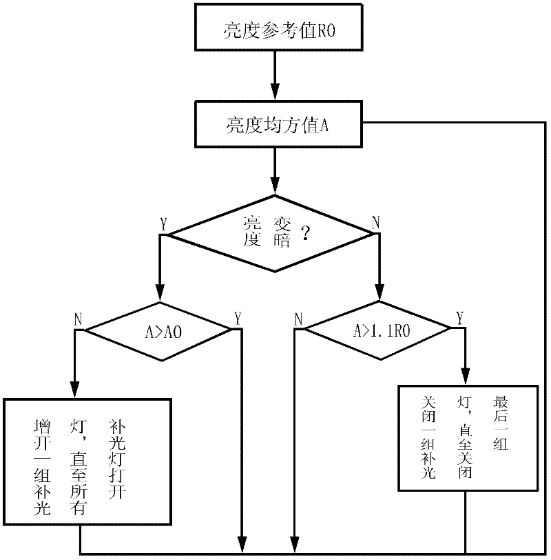
[0034] Step 1: Set the luminance reference value R0 to 120, which is the average luminance value detected by the video signal processing unit 3 of the 8W energy-saving lamp two meters away.

[0035] Step 2: The video signal processing unit 3 obtains the brightness mean square value A according to the image captured by the camera assembly 1, and compares the brightness mean square value A with the standard value R0.

[0036] Step 3: If the brightness mean square value A is greater than the brightness reference value R0, it means that the light is brighter and there is no need for supplementary light, and the video sig...


PUM


Abstract

The invention provides a camera supplementary lighting device comprising a camera assembly arranged in a device main body and a video signal processing unit, wherein the device main body is provided with a light-transmitting plate and an infrared supplementary lighting lamp, corresponding to the camera assembly; the camera assembly is connected with an input end of the video signal processing unit; an output end of the video signal processing unit is electrically connected with a control circuit; and the control circuit is used for controlling the turning-on/off of the infrared supplementary lighting lamp. The control method of the camera supplementary lighting device comprises the following steps of: step 1, setting a brightness reference value R0, wherein R0 is a brightness value when a light brightness reaches the brightness for turning on the infrared supplementary lighting lamp; and step 2, comparing a brightness mean square value A of a pattern photographed by the video signal processing unit according to the camera assembly with the reference value R0. According to the camera supplementary lighting device disclosed by the invention, a special paint coating is additionally arranged to guarantee a supplementary lighting effect of the infrared supplementary lighting lamp, so that an inner circuit board and other parts cannot be observed from the outer part; and meanwhile, the infrared supplementary lighting lamp is divided into a plurality of groups to be controlled and the supplementary lighting brightness can be accurately controlled by combining with the video signal processing unit to process a brightness signal.

Description

technical field [0001] The invention relates to a camera, in particular to a camera light supplement device and a control method thereof. Background technique [0002] The home appliances with video monitoring function in the prior art generally ensure the light transmission effect of the camera supplementary light, and the light transmission area is transparent, so that the internal circuit board and other internal components can be seen from the outside, which is very convenient. It is not beautiful, which is undoubtedly a major shortcoming in the field of home appliances that emphasize appearance. There is only one group under control at the same time. When filling the light, the fill lights are either all on or off; sometimes there will be an embarrassing situation where the fill light is too much when they are all on, and the light intensity is not enough when they are off. The use of photoresistors in brightness detection will not only increase the cost, but also affe...

Claims


Application Information

Patent Timeline
Patent Type & Authority Applications(China)
IPC IPC(8): G03B15/05H04N5/232H04N5/225G03B15/03
Inventor 王斌
Owner MIDEA GRP CO LTD
Why Eureka
Try Eureka