Light guide plate, light guide plate manufacturing method, backlight LED module, display and panel lamp

A technology of light guide plate and backlight source, applied in the field of light guide plate for lighting or display and its preparation, can solve the problems of inability to achieve light guide effect, low uniformity and brightness, low light output efficiency, etc., to meet the requirements of optical design and production. The effect of low cost and cost reduction

Inactive Publication Date: 2015-03-25
陈蕾
View PDF5 Cites 8 Cited by
  • Summary
  • Abstract
  • Description
  • Claims
  • Application Information

AI Technical Summary

Problems solved by technology

[0008] Disadvantages of this technology: the point light source or line light source formed by this type of light guide plate needs an auxiliary diffusion film or diffusion plate to cover the dots or lines on the surface of the light guide plate substrate, and at the same time form a haze-like bright light effect through secondary diffusion
[0014] The existing disadvantages of this technology: because the light guide particles added in the light guide plate are only uniformly distributed, a reasonable optical design cannot be carried out, resulting in low light extraction efficiency and low brightness
Especially in the case of making some large-size light guide plates, the uniformity and brightness are very low, and it is almost impossible to achieve the light guide effect

Method used


Image

  • Light guide plate, light guide plate manufacturing method, backlight LED module, display and panel lamp
  • Light guide plate, light guide plate manufacturing method, backlight LED module, display and panel lamp
  • Light guide plate, light guide plate manufacturing method, backlight LED module, display and panel lamp

Examples


Embodiment 1

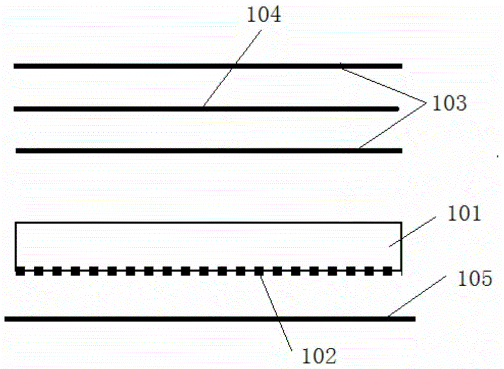
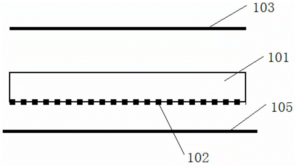
[0058] The light guide plate of this embodiment includes a light guide plate base material, the light guide plate base material is provided with a light incident surface, a light exit surface and a bottom surface, the light exit surface is opposite to the bottom surface, and a layer containing a light guide surface is printed on the light exit surface. The ink film layer of the light particles, the density of the light guide particles in the ink film layer is distributed according to the law of gradually increasing from close to the light source to away from the light source, so as to obtain uniform light output brightness on the light output surface.

[0059] like image 3 and Figure 4 As shown, are respectively the structural schematic diagrams of the light guide plate of this embodiment when applied in LED displays and LED panel lights, and figure 1 and figure 2 Compared with the existing technology, the structure is simplified a lot, for example, there is no need to ar...

Embodiment 2

[0080] The difference between this embodiment and Embodiment 1 lies in that the ink film layer is arranged on the bottom surface of the light guide plate, and other structures can adopt the same structure as Embodiment 1, which will not be repeated here. Compared with Embodiment 1, in this embodiment, a less part of the light entering from the line light source passes through the ink film layer and then directly exits the light emitting surface, while more light exits through the ink film layer after several times of total reflection.

Embodiment 3

[0082] This embodiment is the preparation method of the light guide plate of embodiment 1 and embodiment 2, and its process flow chart is as follows Figure 13 As shown, it mainly includes:

[0083] Step 100 of designing an optical gray scale image, step 200 of making a printing roller 3 , step 300 of preparing printing ink, and step 400 of printing a light guide plate. Wherein, the printing light guide plate step 400 further includes:

[0084] Ink adhesion step 401, that is, rotating the printing roller 3 to make the printing image adhere to the printing ink;

[0085] Ink scraping step 402, that is, the ink scraper 2 scrapes the ink in the non-printing area;

[0086] Transfer printing ink to pad printing roller step 403, that is, transfer the printing pattern to the pad printing rubber roller 5 (the pad printing rubber roller 5 and the printing roller 3 move in the opposite direction);

[0087] Printing step 404, that is, transfer the pattern to the light guide plate subst...


PUM

PropertyMeasurementUnit
particle diameteraaaaaaaaaa
hardnessaaaaaaaaaa

Abstract

The invention provides a light guide plate, a light guide plate manufacturing method, a backlight LED module, a display and a panel lamp. The light guide plate includes a light guide plate base material, the light guide plate base material is provided with a light inlet surface, a light outlet surface and a bottom surface, wherein the light outlet surface is opposite to the bottom surface, in addition, the light outlet surface or the bottom surface is provided with an ink film layer, and light guide particles are distributed in the ink film layer according to a predetermined law. The ink film layer containing the light guide particles is printed on the light outlet surface, the light guide particles in the ink film layer are distributed according to the law that the density of the light guide particles gradually increases in the direction from the position close to a light source to the position away from the light source, in this way, an auxiliary diffusion plate or an auxiliary diffusion film is omitted, light loss is reduced by 10% or so, and the product cost is lowered; moreover, as a linear light source is directly converted into the surface light source, uniform outlet light brightness which cannot be achieved in the prior art can be achieved through the light guide plate, and the requirement of large-size light guide plates and complex optical design requirements can be satisfied.

Description

technical field [0001] The invention relates to lighting or display equipment, in particular to a light guide plate for lighting or display, a preparation method and special equipment. Background technique [0002] Light guide plates are widely used in various display products, such as televisions, monitors, and various digital terminals. With the development of LED lighting technology, light guide plates are also widely used in panel lights and ultra-thin advertising light boxes. The production principle of the light guide plate is to guide the light to the direction where the light needs to be emitted by destroying the total reflection of light in the high-density light guide substrate, and convert the line light source that enters the light from the side into a planar light source. From the principle of process method, the production technology of light guide plate is mainly divided into two categories: [0003] The first category: surface treatment technology, its ligh...

Claims


Application Information

Patent Timeline
Patent Type & Authority Applications(China)
IPC IPC(8): G02B6/00F21S8/00F21V8/00B41M1/26B41M5/00F21Y101/02
CPCB41M1/26B41M5/0041F21Y2101/00G02B6/004
Inventor 陈蕾
Owner 陈蕾
Why Eureka
Try Eureka