
A Design Method of DC Ice-melting Device with Special Converter Transformer

A converter transformer, DC ice melting technology, applied in overhead installation, cable installation, flexible AC transmission system and other directions, can solve the problem of no design method and so on

Active Publication Date: 2015-08-19
ELECTRIC POWER RESEARCH INSTITUTE, CHINA SOUTHERN POWER GRID CO LTD
View PDF5 Cites 0 Cited by
  • Summary
  • Abstract
  • Description
  • Claims
  • Application Information

AI Technical Summary

Problems solved by technology

[0010] In view of the fact that the DC ice melting device is not used for ice melting for a very long time each year, it generally has the function of a static var compensation device in practical applications, and no complete design method has yet been proposed.

Method used


Image

  • A Design Method of DC Ice-melting Device with Special Converter Transformer
  • A Design Method of DC Ice-melting Device with Special Converter Transformer
  • A Design Method of DC Ice-melting Device with Special Converter Transformer

Examples


Embodiment 1

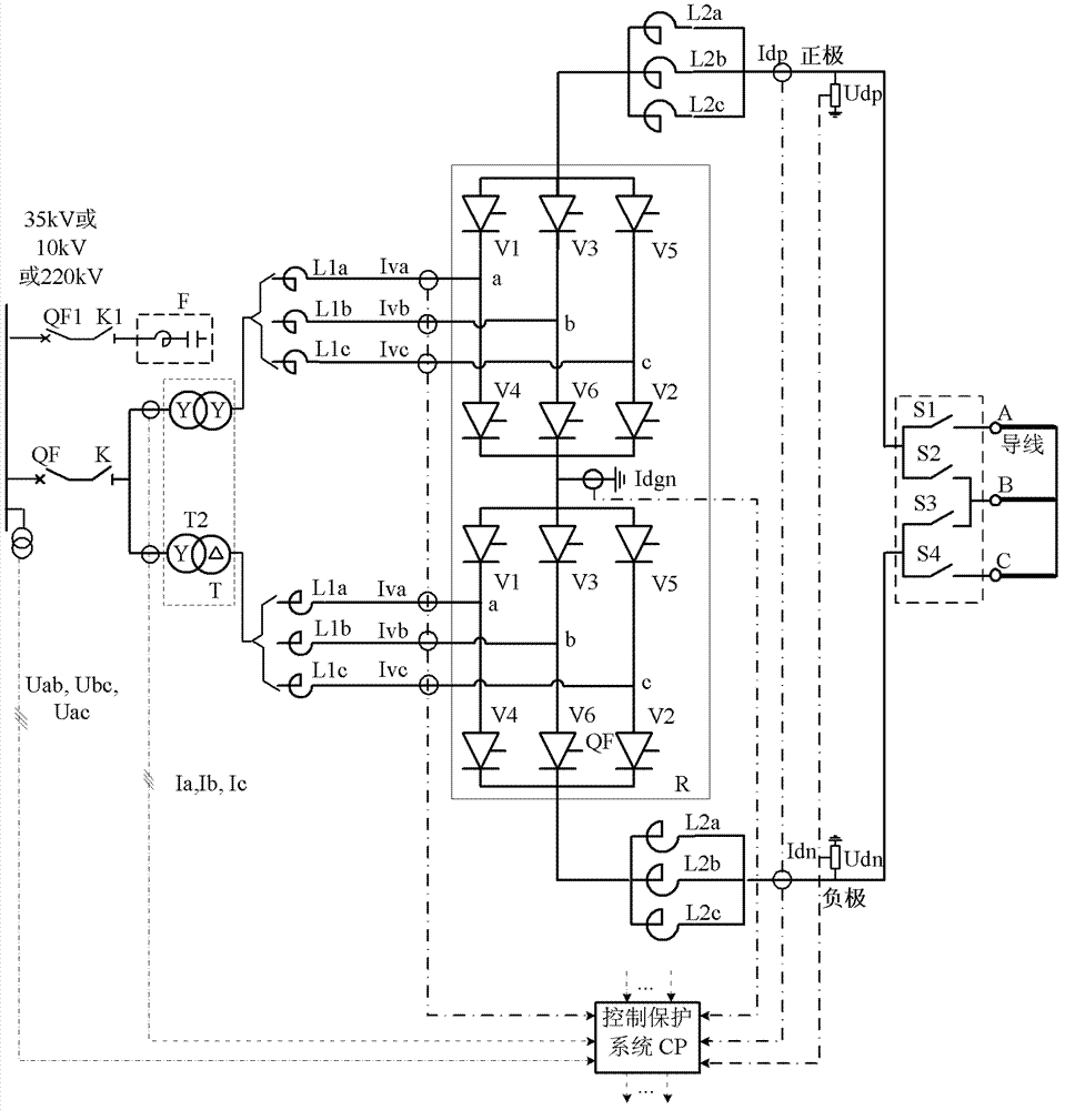
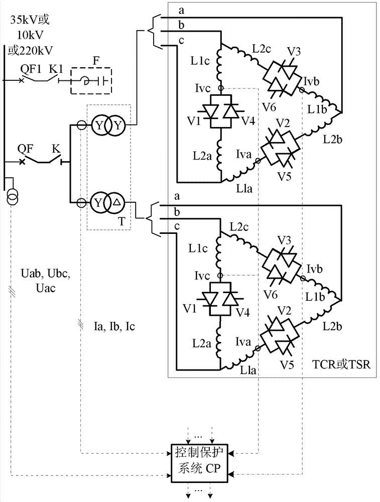
[0106] The structural diagram of the 12-pulse DC ice-melting and reactive power compensation device with special converter transformer of the present invention is as follows: figure 1 , 2As shown, in this embodiment, there are two dedicated converter transformers T (one is Y / Y connection, the other is Y / Δ connection), two groups of reactors L1a, L1b, L1c, two groups of six-pulse Converter R, two sets of reactors L2a, L2b, L2c, knife switches S1, S2, S3, S4, control and protection system CP, AC filter bank F, reactors L1a, L1b, L1c are The commutation reactance is a part of the thyristor controlled reactor TCR or the thyristor switching reactor TSR in the reactive power compensation mode, and the reactors L2a, L2b, and L2c are all connected in parallel as smoothing reactors in the DC deicing mode. In the power compensation mode, it is a part of the thyristor controlled reactor TCR or the thyristor switching reactor TSR; The DC transformer T is connected to form a twelve-pulse...

Embodiment 2

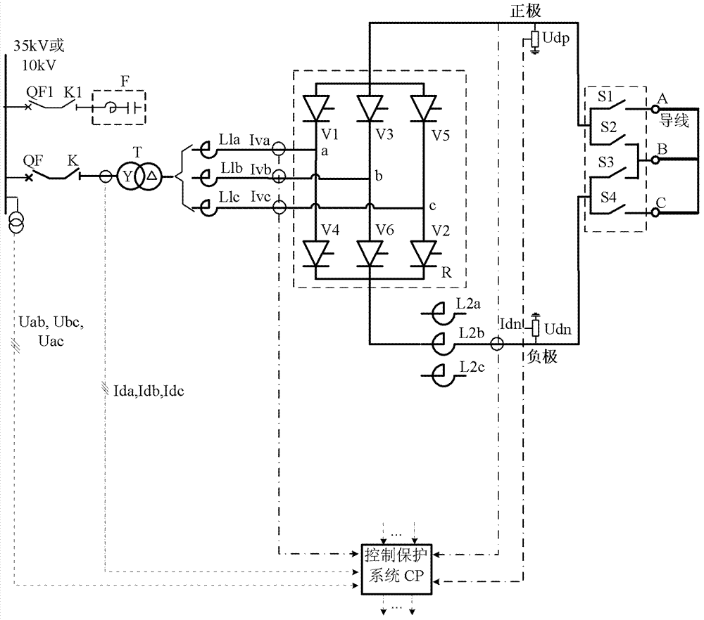
[0174] The structural diagram of the six-pulse DC ice-melting and reactive power compensation device with special converter transformer of the present invention is as follows: image 3 , 4 As shown, in this embodiment, a dedicated converter transformer T (Y / Δ connection), a set of reactors L1a, L1b, L1c, a set of six-pulse converter R, a set of reactors L2a, L2b, L2c, knife switch S1, S2, S3, S4, control and protection system CP, AC filter bank F, reactors L1a, L1b, L1c are commutation reactors in DC ice melting mode, and thyristor control in reactive power compensation mode Reactor TCR or a part of thyristor switching reactor TSR, reactors L2a, L2b, L2c are all smoothing reactors in the next phase of DC ice melting mode, and are thyristor controlled reactors TCR or thyristor switching in reactive power compensation mode Cut off part of the reactor TSR; in the DC ice-melting mode, the AC side of the six-pulse converter R is connected to the dedicated converter transformer T t...


PUM


Abstract

The invention discloses a design method of a direct-current ice melting device with a special converter transformer. The design method comprises the following steps: 1) determining a covering path of the ice melting device; 2) pre-selecting ice melting current of a lead wire; 3) determining maximal allowed current of the lead wire; 4) calculating direct-current voltage drop and power under the pre-selected ice melting current; 5) determining rated parameters of the ice melting device; 6) calculating ideal no-load direct-current voltage; 7) calculating commutation reactor valve side rated voltage; 8) calculating converter transformer and commutation reactor side rated voltages; 9) calculating converter alternating-current side rated current; 10) calculating inductance of the commutation reactor; 11) calculating rated capacity of the converter transformer; 12) calculating inductive impedance of the converter transformer; 13) determining rated capacity and current of a TCR (Thyristor Controlled Reactor) or TSR (Thyristor Switched Reactor) branch circuit; 14) determining total inductive impedance value of the TCR or TSR branch circuit; 15) determining inductance value needed to be increased of the TCR or TSR branch circuit; 16) determining zero-power loop inductance; 17) determining zero-power minimal allowed current; and 18) designing an alternating-current filter.

Description

technical field [0001] The invention relates to a design method of a DC deicing device with a special converter transformer, in particular to a design method involving a comprehensive consideration of DC deicing and its equivalent test, a thyristor controlled reactor (TCR) or a thyristor switching reactor (TSR) It belongs to the innovative technology of DC ice melting and static var compensation application of high-voltage and ultra-high voltage power grid transmission lines. Background technique [0002] Icing of transmission lines in winter seriously threatens the safe operation of the power system. Due to the increased ice load on the conductors, it will cause certain mechanical damage to the conductors, iron towers and fittings. When the ice is severe, the wires will be broken and the towers will fall, resulting in large-scale power outages and great losses to the national economy. [0003] As the global climate continues to deteriorate, the damage caused by ice disaste...

Claims


Application Information

Patent Timeline
Patent Type & Authority Patents(China)
IPC IPC(8): H02G7/16H02J3/18
CPCY02E40/12Y02E40/10
Inventor 傅闯饶宏许树楷黎小林
Owner ELECTRIC POWER RESEARCH INSTITUTE, CHINA SOUTHERN POWER GRID CO LTD
Learn More