
Flow forwarding method and device

A technology of traffic forwarding and traffic distribution group, which is applied in the field of network communication and can solve problems such as inability to apply mesh networking, bundling, and indeterminacy.

Active Publication Date: 2012-07-18
NEW H3C TECH CO LTD
View PDF2 Cites 42 Cited by
  • Summary
  • Abstract
  • Description
  • Claims
  • Application Information

AI Technical Summary

Problems solved by technology

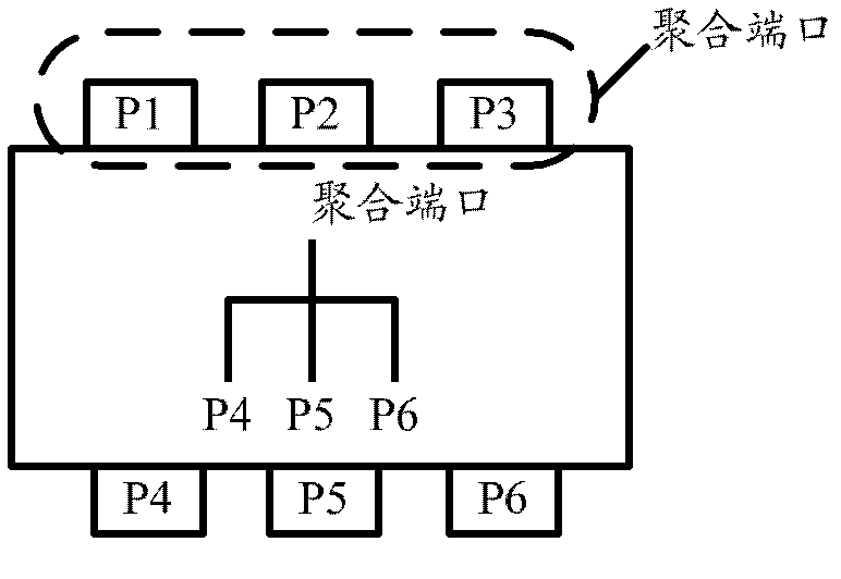
[0004] In the existing technology, in order to ensure traffic forwarding, the aggregation port and its member ports are strictly bound, and a physical port can only be bound to one aggregation port, that is, a physical port belongs to only one aggregation port and cannot belong to More than two aggregated ports, for example, figure 1 The physical ports P1, P2, and P3 in the physical port only belong to aggregated port 1, and they cannot belong to other aggregated ports. Otherwise, it will be impossible to determine which aggregated traffic should be marked with the inbound traffic received by the physical port P1, P2, or P3. Port marking, which makes the inbound traffic unable to continue forwarding
[0005] However, a physical port belongs to only one aggregation port, which limits the ability of a physical port to carry ECMP in Layer 2 Equal Cost Multipath (L2ECMP) technology, for example, figure 1 Among them, P1 to P3 are bundled together to form an aggregation port, and if P3 and P4 are the egress ports through which ECMP reaches the destination, P3 and P4 cannot be bundled together, which will obviously limit the ability of P3 to carry ECMP. As a result, L2ECMP can only be used in aggregation uplink or downlink networking scenarios, and cannot be applied to mesh networking

Method used


Image

  • Flow forwarding method and device
  • Flow forwarding method and device
  • Flow forwarding method and device

Examples


Embodiment Construction

[0027] In order to make the object, technical solution and advantages of the present invention clearer, the present invention will be described in detail below in conjunction with the accompanying drawings and specific embodiments.

[0028] In the prior art, since the aggregated port is formed by bundling multiple physical ports, this restricts the strict binding between the aggregated port and the member ports. A physical port can only be bound to one aggregated port. Otherwise, if a physical Ports are bound to two or more aggregated ports at the same time, which will cause traffic forwarding confusion.

[0029] And in the present invention, do not bind the physical port on the switching device, it divides the physical port on the switching device with ECMP as the focus, the method provided by the present invention is analyzed below:

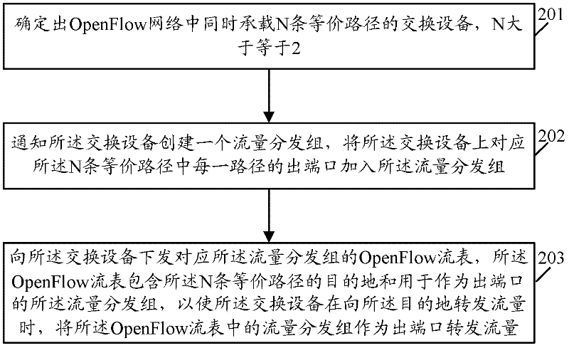
[0030] see figure 2 , figure 2 The flow chart of the method provided by the embodiment of the present invention. The method is applied to...


PUM


Abstract

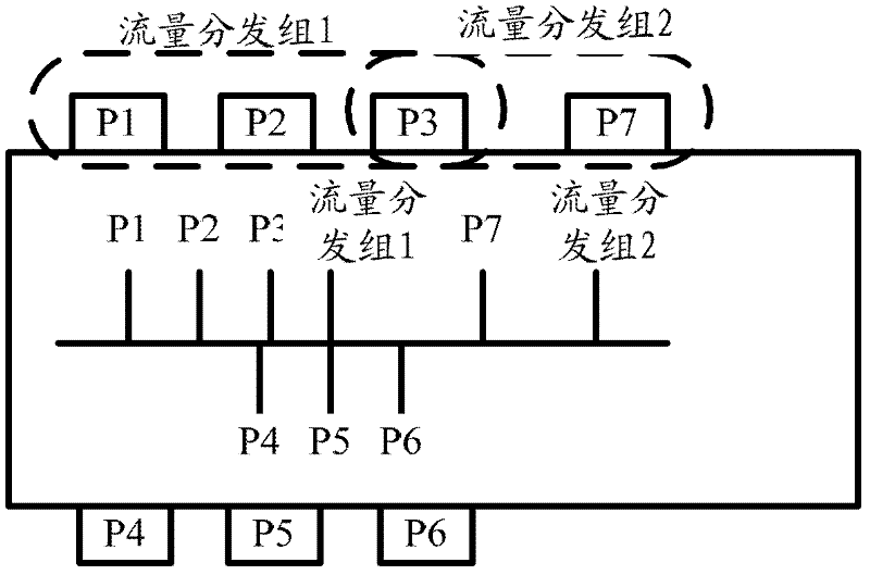
The invention provides a flow forwarding method and a flow forwarding device. The method is applied to an Openflow Controller in an OpenFlow network and comprises the following steps: A, determining exchange equipment for simultaneously bearing N equivalent paths in the OpenFlow network; B, notifying the exchange equipment of creating a flow distribution group, adding an output port corresponding to each path in the N equivalent paths on the exchange equipment into the flow distribution group; and C, distributing a first OpenFlow meter corresponding to the flow distribution group to the exchange equipment, wherein the first OpenFlow meter contains destinations of the N equivalent paths and is used for the flow distribution group as the output port, so that when the exchange equipment forwards the flow to the destinations, the flow distribution group in the first OpenFlow meter is used as the output port to forward the flow.

Description

technical field [0001] The invention relates to network communication technology, in particular to a traffic forwarding method and device. Background technique [0002] Port aggregation is to bind two or more physical ports on the switching device together to form an aggregation port through configuration software settings, and each physical port that forms the aggregation port is called a member port. Among them, the aggregation port combines the bandwidth of each member port to provide a high bandwidth several times that of each member port. [0003] see figure 1 , figure 1 It is a schematic diagram of a port on a switching device. exist figure 1 In this example, in order to increase the network bandwidth between the local network node and the peer end, the physical ports P1, P2, and P3 on the local switching device are bundled together to form an aggregation port 1. so, such as figure 1 As shown, the switching device has four ports at the forwarding level, namely: P...

Claims


Application Information

Patent Timeline
IPC IPC(8): H04L12/56H04L47/41H04L45/74
CPCH04L45/64Y02B60/33H04L45/245Y02D30/50H04L45/745H04L49/253
Inventor 常慧锋
Owner NEW H3C TECH CO LTD
Learn More