Rotary compressor

A rotary compressor and compressor technology, applied in the field of compressors, can solve the problems of difficult compressor design and assembly, and achieve the effect of reducing the overall height and size, and eliminating the need for rolling parts

Inactive Publication Date: 2012-07-18
泰康产品公司
View PDF6 Cites 10 Cited by
  • Summary
  • Abstract
  • Description
  • Claims
  • Application Information

AI Technical Summary

Problems solved by technology

Thus, the size of the counterweight makes the design and assembly of such compressors increasingly difficult

Method used


Image

  • Rotary compressor
  • Rotary compressor
  • Rotary compressor

Examples


Embodiment Construction

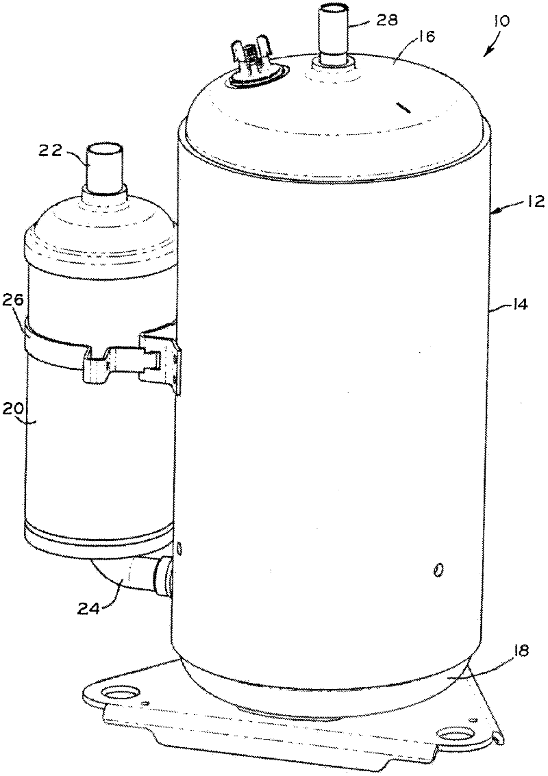
[0023] figure 1 A rotary compressor 10 forming one embodiment of the present invention is shown. Compressor 10 includes an outer hermetic casing 12 including a central portion 14 to which an upper cover 16 and a lower cover 18 are attached, for example by welding. The central portion 14 of the compressor 10 is connected by a mounting strap 26 to a conventional suction accumulator 20 having an inlet 22 and an outlet suction pipe 24 . The compressed refrigerant is discharged from the high pressure housing 12 via the discharge pipe 28 . The compressor 10 may be part of a heating circuit and / or a cooling circuit and is used to compress a working fluid such as a refrigerant such as a hydrofluorocarbon refrigerant, a chlorofluorocarbon refrigerant, a hydrochlorofluorocarbon refrigerant, or carbon dioxide refrigerant.

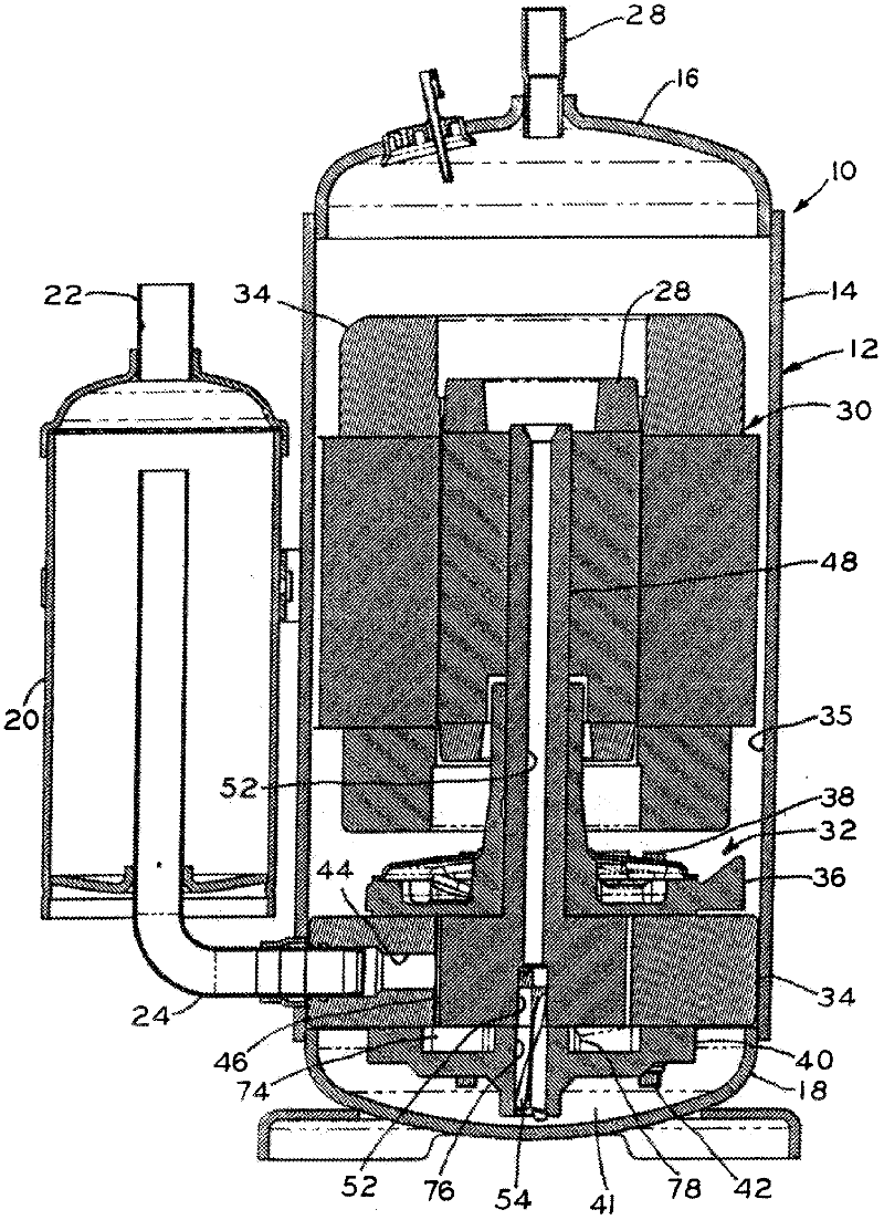
[0024] now go to Figure 3 to Figure 5 , a motor 30 and a compression mechanism 32 are installed in the sealed housing 12 . An oil sump 41 ( image 3 ). The mo...


PUM


Abstract

The eccentric on the crankshaft of a rotary compressor, as well as the roller that surrounds the crankshaft, is replaced by an elliptical cam that acts as a double eccentric. In this manner, the elliptical cam provides for proper balancing of the crankshaft and other components of the compressor, while eliminating the need to use counterweights. Specifically, the elliptical cam is symmetrical, resulting in equal forces acting on opposing sides of the elliptical cam. This allows the elliptical cam to maintain its balance throughout its rotation, even when operating at a high rate of revolution.

Description

[0001] Cross References to Related Documents [0002] This application claims the benefit of U.S. Provisional Patent Application No. 61 / 246,319, filed September 28, 2009, entitled "Rotary Compressors," pursuant to U.S.C § 119(e) Section 35, the entire disclosure of which expressly incorporated herein by reference. technical field [0003] The present invention relates to a compressor, in particular to a rotary compressor. Background technique [0004] In a rotary compressor, the compression mechanism includes an eccentric disposed within a cylindrical compression chamber. Vanes extending from the cylindrical wall of the compression chamber contact rolling members disposed around the eccentric, dividing the compression chamber into a compression chamber and a suction chamber. As the eccentric, and correspondingly the rolling member, moves through the compression chamber, the volume of the compression chamber is reduced to compress the working fluid contained within the comp...

Claims


Application Information

Patent Timeline
Patent Type & Authority Applications(China)
IPC IPC(8): F04C29/00F04C18/356F04C29/02
CPCF04C29/0042F04C23/008F04C18/356
Inventor 唐纳德·L·科菲詹姆斯·R·伦兹
Owner 泰康产品公司
Why Eureka
Try Eureka