Supercharge Your Innovation With Domain-Expert AI Agents!

Power connection conductor

A technology for connecting conductors and electric power, applied in the direction of conductive connection, connection, switch terminal/connection, etc., can solve the problems of wiring errors and complicated wiring, etc., reduce wiring errors, improve work efficiency, and reduce wiring assembly work volume effect

Active Publication Date: 2015-03-25
TOKYO ELECTRON LTD
View PDF9 Cites 0 Cited by
  • Summary
  • Abstract
  • Description
  • Claims
  • Application Information

AI Technical Summary

Problems solved by technology

In addition, wiring becomes complicated accordingly, and there is a problem of causing wiring errors

Method used


Image

  • Power connection conductor
  • Power connection conductor
  • Power connection conductor

Examples


Embodiment Construction

[0056] Hereinafter, embodiments of the present invention will be described with reference to the drawings.

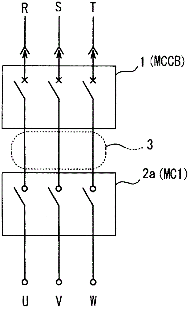
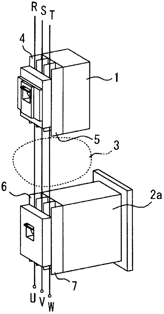
[0057] figure 1 , figure 2 It is a wiring diagram showing a part of the wiring breaker 1 and a part of the first electromagnetic switcher 2a for the branch of the three-phase load side branch that are wired in the distribution board (not shown) and fixedly installed. Three-phase R, S, T for power supply from the primary side terminal part 4 of the circuit breaker 1 (MCCB), and the primary side connection terminal part connected from the secondary side terminal part 5 to the first electromagnetic switch 2a (MC1) 6 and the three-phase wires of R (red), S (white), and T (black) that are also visually separated in color are connected to the secondary side connection terminal portion 7 of the first electromagnetic switch 2a, and are connected to the electrical load. side power supply.

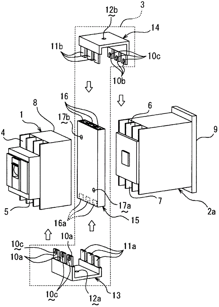
[0058] Such as image 3 As shown, as a positional relationship fixedly arranged in t...


PUM


Abstract

Provided is a power connection conductor that makes it possible to compactly store circuit breakers and electromagnetic switches in a power distribution board without resulting in an increase in the area of the power distribution board and without performing complex wiring work. Said power connection conductor also reduces wiring mistakes and the number of man-hours required for wiring. In order to connect a circuit breaker to connection terminals on an electric device such as an electromagnetic switch (2a, 2b), the power connection conductor has conducting bars integrally formed from electrical wires, for a plurality of power phases, enclosed inside an insulating member. The power connection conductor has a flat plate-shaped base section disposed, at least, between the anchoring side of a circuit breaker and the front side of an electromagnetic switch. Conducting bars on both ends of the flat plate-shaped base section are connected, respectively, to secondary connection terminals on the circuit breaker and primary connection terminals on the electromagnetic switch.

Description

technical field [0001] The present invention relates to a connecting conductor for electric power provided in a distribution board, for example, for electrically wiring connection to electronic equipment such as a circuit breaker and an electromagnetic switch for wiring. Background technique [0002] Generally, there is known a distribution circuit breaker (MCCB: Molded Case Circuit Breaker) in which, for example, three-phase 200V wires connected to the electrical load side of the main distribution circuit breaker are connected to the electrical load side of the main distribution circuit breaker. (molded case circuit breaker)) and the primary side of the electromagnetic switch (Electromagnetic Contact: electromagnetic contactor) connected below it are arranged in parallel in a straight line in the distribution board, and the terminals of the two are connected using wires. Power the electronics on the load side. [0003] In addition, in the circuit breaker for main wiring, t...

Claims


Application Information

Patent Timeline
Patent Type & Authority Patents(China)
IPC IPC(8): H02B1/20H01H73/20H02B1/40
CPCH01R4/48H01H89/06H01R9/2466H01H71/08H01H73/20H02B1/20H02B1/40
Inventor 一宫贤治川野利行佐藤尊三
Owner TOKYO ELECTRON LTD
Features
  • R&D
  • Intellectual Property
  • Life Sciences
  • Materials
  • Tech Scout
  • Unparalleled Data Quality
  • Higher Quality Content
  • 60% Fewer Hallucinations
Learn More