Substrate backing device and substrate thermocompression bonding device

A backing plate and substrate technology, applied in the direction of workpiece clamping devices, electrical components, manufacturing tools, etc., can solve the problems of rising equipment costs and difficulty in ensuring connection quality, so as to ensure connection quality, stabilize connection quality, and improve followability Effect

Active Publication Date: 2017-02-15
PANASONIC INTELLECTUAL PROPERTY MANAGEMENT CO LTD
View PDF2 Cites 0 Cited by
  • Summary
  • Abstract
  • Description
  • Claims
  • Application Information

AI Technical Summary

Problems solved by technology

[0012] However, in order to achieve high-precision control of the pressure bonding load at the time of thermocompression bonding with a known thermocompression bonding device in response to the increase in the density of rigid substrates, the configuration of the thermocompression bonding device cannot be avoided. , leading to an increase in equipment costs
In addition, in order to accurately control the crimping load during thermocompression bonding with known thermocompression bonding equipment, precise control of pressing force is required, so it is difficult to ensure stable connection quality

Method used


Image

  • Substrate backing device and substrate thermocompression bonding device
  • Substrate backing device and substrate thermocompression bonding device
  • Substrate backing device and substrate thermocompression bonding device

Examples


no. 1 Embodiment approach

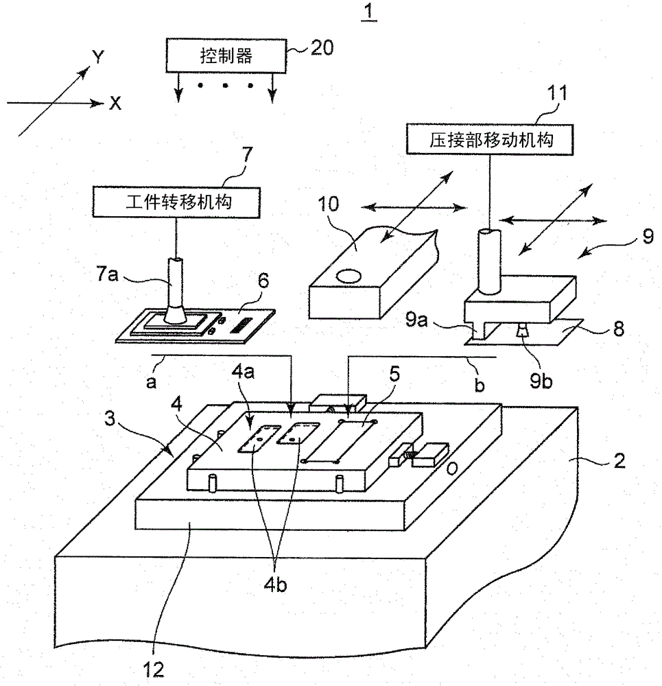
[0050] First, refer to figure 1 Next, the configuration and functions of the substrate thermocompression bonding device 1 provided with the substrate backing device 3 according to the first embodiment of the present invention will be described. The substrate thermocompression bonding apparatus 1 has a function of pressing a flexible substrate 8 that is a flexible second substrate to an edge portion of a rigid substrate 6 that is a hard first substrate to perform thermocompression bonding. The thermocompression bonding apparatus 1 in this embodiment includes a workpiece transfer device 7 , a crimping unit 9 , an imaging unit 10 , and a crimping movement mechanism 11 in addition to the substrate backing device 3 . Furthermore, the thermocompression bonding apparatus 1 includes a controller 20 that controls the operation of the entire apparatus including the substrate backing apparatus 3 , the workpiece transfer apparatus 6 , the imaging unit 10 , and the pressure bonding movemen...

no. 2 Embodiment approach

[0084] Figure 10 The configuration of the receiving member 21 of the second embodiment shown is different from that of the first embodiment. Specifically, as Figure 11 As shown, the receiving member 21 in this embodiment includes a single rebound member 21a. The rebounding member 21 is made of elastic body such as resin or rubber, sponge, felt, etc., which can freely expand and contract by external force, generate a predetermined rebound force according to the degree of compression, and return to the original shape when the external force is removed. A plurality of slits 22a, 22b are provided in the substantially flat rectangular parallelepiped rebounding member 21a from the upper surface toward the lower surface. Specifically, the slits 22a are straight lines extending in the width direction in the drawing, and are arranged at equal intervals from each other. In addition, the slits 22b are straight lines extending in the depth direction in the figure, and are arranged at...


PUM


Abstract

A substrate backing device places and holds a rigid substrate thereon and receives, from therebelow, a pressing force during operations for thermocompressively bonding a flexible substrate thereto. The substrate backing device includes a plate-shaped backing plate provided with a backing support surface adapted to come into contact with the lower surface of the rigid substrate for supporting it. The backing support surface is provided with an opening portion having a planar opening shape encompassing the area of the rigid substrate to be compressively bonded to the flexible substrate. The backing support surface is provided, within the opening portion, a receiving member which, during the thermocompression bonding operations, come into contact with the lower surface of the rigid substrate and with an already-mounted component having been preliminarily mounted on this lower surface in the compression-bonding area and, further, apply an upward supporting counterforce corresponding to the pressing force.

Description

technical field [0001] The present invention relates to a substrate backing device (Substrate Backing Device) and a substrate thermocompression bonding device using the substrate backing device. In particular, the present invention is suitable for thermocompression bonding of a flexible first substrate such as a film-like flexible substrate to a hard second substrate such as a rigid substrate. Background technique [0002] In electronic devices that require miniaturization and high functionality, such as mobile phones, a configuration in which functional modules such as a CCD camera and a display panel are connected to a main electronic circuit module provided on a rigid substrate via a film-shaped flexible substrate is generally used. . As a method of connecting a terminal provided on a flexible substrate to a circuit electrode provided on a rigid substrate, a connection method using a conductive adhesive containing conductive particles such as solder in a thermosetting re...

Claims


Application Information

Patent Timeline
Patent Type & Authority Patents(China)
IPC IPC(8): H05K13/04
CPCB25B11/005Y10T156/17Y10T156/1744Y10T156/1756
Inventor 圆尾弘树本村耕治永福秀喜境忠彦
Owner PANASONIC INTELLECTUAL PROPERTY MANAGEMENT CO LTD
Why Eureka
Try Eureka