

Safe falling protector for vertical ladder
A fall arrester and safety technology, applied in safety belts, life-saving equipment and other directions, can solve the problem of inconvenient installation of the fall arrester, and achieve the effect of convenient disassembly and assembly process.
- Summary
- Abstract
- Description
- Claims
- Application Information
AI Technical Summary
Problems solved by technology
Method used
Image

Examples
Embodiment Construction
[0030] The preferred embodiments of the present invention are given below in conjunction with the accompanying drawings to describe the technical solution of the present invention in detail.
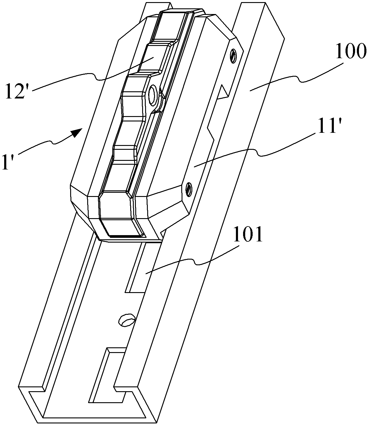
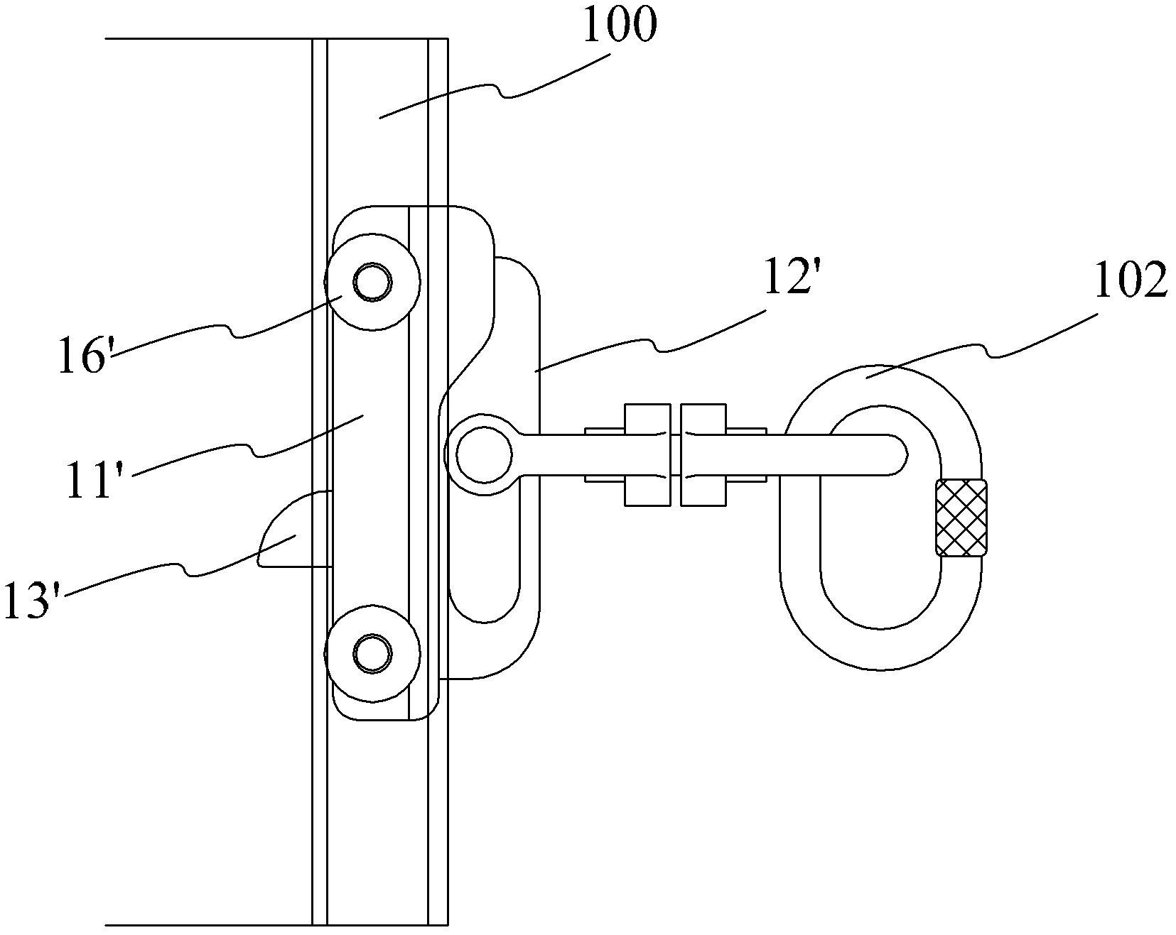
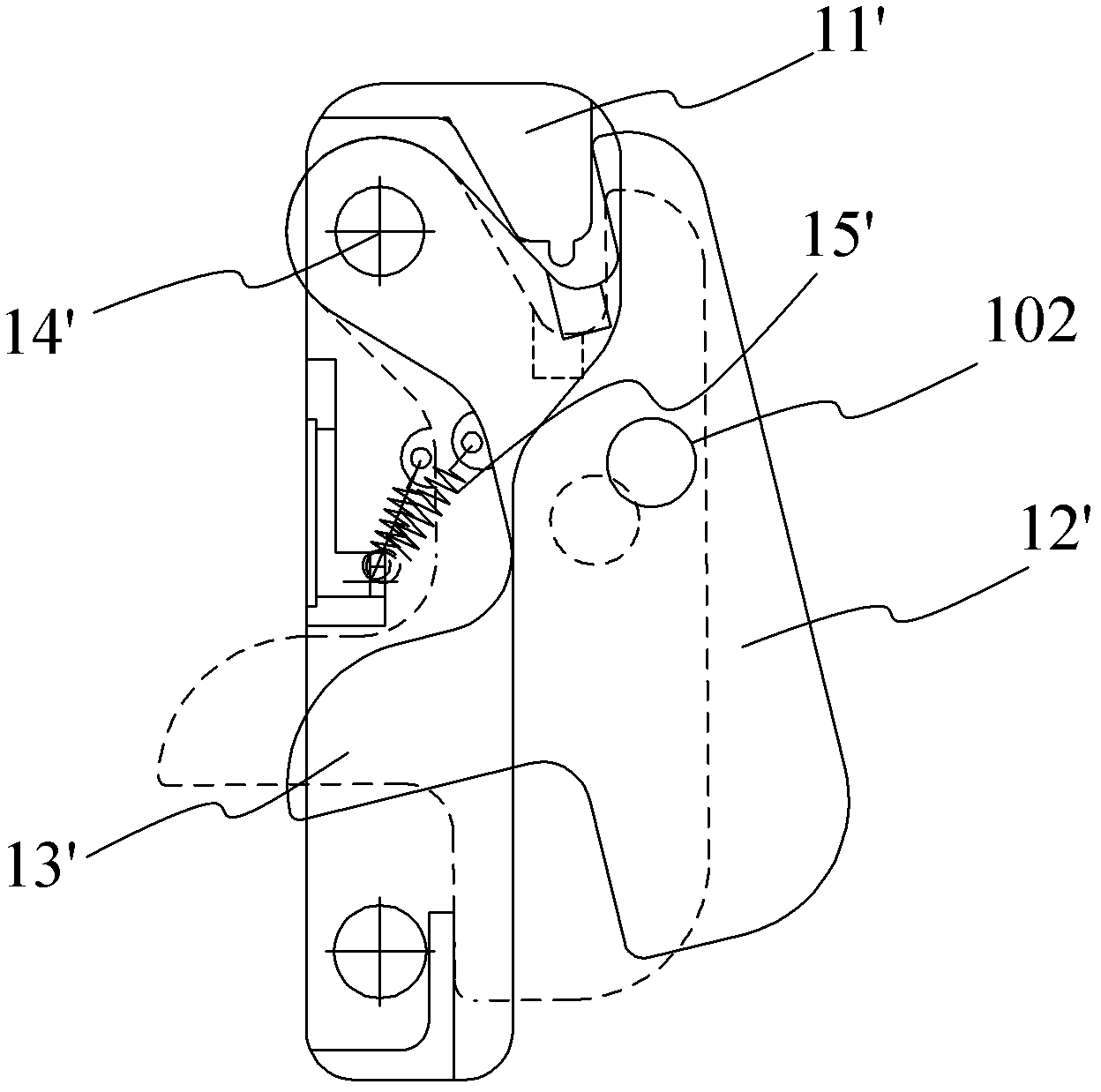
[0031] Such as Figure 4 and Figure 5 As shown, the safety fall arrester 1 for a straight ladder of the present invention includes a slider seat 11 and a slider 12 rotatably connected to a groove (not shown) on the slider seat 11 . Such as Figure 6 As shown, a rotating shaft 21 is passed through the upper end of the slider 12, and is rotatably connected to the upper end of the groove through the rotating shaft 21 . A torsion spring 22 is sheathed on the rotating shaft 21 , the upper end of the torsion spring 22 is pressed against the upper end of the slider 12 , and the lower end of the torsion spring 22 is pressed against the upper end of the groove. A convex portion 121 is provided on the surface of the slider 12 directed to the slider seat 11, and the convex portion 121 is adapte...
PUM
 Abstract
Description
Claims
Application Information