Monitor mounting and fixing device

A fixing device and monitor technology, applied in the electronic field, can solve problems such as complicated operation and easily damaged ceiling, and achieve the effects of convenient operation, prevention of rotation and displacement, and simple structure

Inactive Publication Date: 2012-07-25
QISDA SUZHOU +1
View PDF4 Cites 10 Cited by
  • Summary
  • Abstract
  • Description
  • Claims
  • Application Information

AI Technical Summary

Problems solved by technology

[0002] At present, a commonly used installation method for security monitoring systems used indoors is called flush mount, that is, dig a hole on the ceiling enough to place the monitor, and use the edge mechanism (usually circular) of the monitor to snap Leaning against the ceiling without falling, this instal

Method used


Image

  • Monitor mounting and fixing device
  • Monitor mounting and fixing device
  • Monitor mounting and fixing device

Examples


Embodiment 1

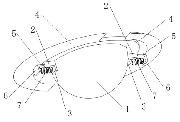
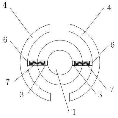
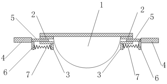
[0023] In this embodiment, a monitor installation and fixing device is used to install the monitor on the installation panel, such as Figure 1~Figure 3 As shown, it includes a hemispherical monitor body 1. The bottom edge of the monitor body 1 is provided with two evenly distributed horizontal chute 2, and each chute 2 is vertically provided with a main stop near one end of the monitor body 1. Block 3; chute 2 and main block 3 are integrally formed. It also includes a telescopic bracket 4. The telescopic bracket 4 is composed of two arc-shaped airfoils surrounding the bottom edge of the monitor main body 1. Each airfoil is integrally provided with a chute 2 extending toward the center of the monitor body 1. The slide rail 5 that slides relatively in the center; the joint between the slide rail 5 and the telescopic support 4 is vertically provided with a secondary stopper 6 corresponding to the main stopper, and the slide rail 5 and the secondary stopper 6 are integrally forme...

Embodiment 2

[0027] This embodiment is similar in structure to Embodiment 1, as Figure 4~Figure 5 As shown, the difference is that a screw hole 8 is provided at both ends of the airfoil of the telescopic support 4 respectively; The perforation 10, the bolt passes through the perforation 10 and the installation panel, and is screwed into the screw hole 8, so that the monitor installation fixture is fixed on the installation panel. Before the bolts are tightened and fixed, the round and rotatable characteristics of the monitor installation and fixture can be used to rotate the angle of the monitor. After tightening, it can be fixed on the installation panel to prevent its rotation and displacement, which is simple and convenient.

Embodiment 3

[0029] This embodiment is similar in structure to Embodiment 1, as Figure 6 As shown, the difference is that the airfoil of the telescopic support 4 is integrally formed with a fixing part 9, and the fixing part 9 and the airfoil are combined to form a clamping part 11, and the cross section of the clamping part 11 is U-shaped. The direction of the opening is outward, and the size of the opening is at least the same as the thickness of the mounting panel. Four pairs of screw holes 8 and perforations 10 are provided at the corresponding positions of the airfoil of the clamping part 11 and the fixing part 9. The bolts pass through the perforations 10 and the mounting panel, and are screwed into the screw holes 8 to fix the monitor installation fixture on the installation panel.


PUM


Abstract

The invention discloses a monitor mounting and fixing device, comprising a hemispherical monitor body and a flexible bracket. The bottom edge of the monitor body is provided with at least one horizontal chute; one end of each chute, which is close to the monitor body, is vertically provided with a main baffle plate; the flexible bracket is formed by aerofoil-shaped plates corresponding to the chute and surrounded at the bottom edge of the monitor body; each aerofoil-shaped plate is integrally provided with a slide rail extending towards the center of the monitor body and sliding relatively in each chute; the joint of each slide rail and the aerofoil-shaped plate is vertically provided with an auxiliary baffle plate corresponding to the main baffle plate; and the corresponding auxiliary baffle plate and main baffle plate are connected through a spring. The spring is used to drive the flexible bracket so as to from the monitor mounting and fixing device with variable diameter. The monitor mounting and fixing device is simple in structure and convenient to operate.

Description

technical field [0001] The invention relates to the field of electronics, in particular to a monitor installation and fixing device. Background technique [0002] At present, a commonly used installation method for security monitoring systems used indoors is called flush mount, that is, dig a hole on the ceiling enough to place the monitor, and use the edge mechanism (usually circular) of the monitor to snap Leaning against the ceiling without falling, this installation method and the structural design of the old monitoring system, in addition to digging a hole in the ceiling, you also need to dismantle the ceiling, place the monitor from the back of the ceiling, and then install it back on the ceiling , so the operation is more complicated and easy to damage the ceiling. Contents of the invention [0003] In view of the above-mentioned defects in the prior art, the object of the present invention is to propose a monitor installation and fixing device that is simple in st...

Claims


Application Information

Patent Timeline
IPC IPC(8): F16M11/04F16M13/02H04N5/225
Inventor 萧启宏
Owner QISDA SUZHOU
Why Eureka
Try Eureka