
Distribution transformer based on glass fiber tape winding

A technology of distribution transformer and glass fiber tape, which is applied in the direction of transformer/inductor magnetic core, transformer/inductor parts, transformer/inductor coil/winding/connection, etc. Harm, damage to the insulator and other problems, to avoid rotational displacement, high tensile strength, good insulation effect

Inactive Publication Date: 2017-07-25
YUNNAN POWER GRID CO LTD ELECTRIC POWER RES INST +1
View PDF5 Cites 0 Cited by
  • Summary
  • Abstract
  • Description
  • Claims
  • Application Information

AI Technical Summary

Problems solved by technology

At the same time, since the distribution transformer will vibrate during the working process, the long-term vibration will cause the iron core to undergo rotational displacement. Only the setting of iron core fasteners cannot avoid the rotational displacement of the iron core.
The deformation of the distribution transformer winding and the rotational displacement of the iron core will change the internal insulation distance of the distribution transformer and damage the insulator, resulting in partial discharge of the distribution transformer and a decline in mechanical performance, which will bring serious damage to the entire distribution system. harm

Method used


Image

  • Distribution transformer based on glass fiber tape winding
  • Distribution transformer based on glass fiber tape winding
  • Distribution transformer based on glass fiber tape winding

Examples


Embodiment 1

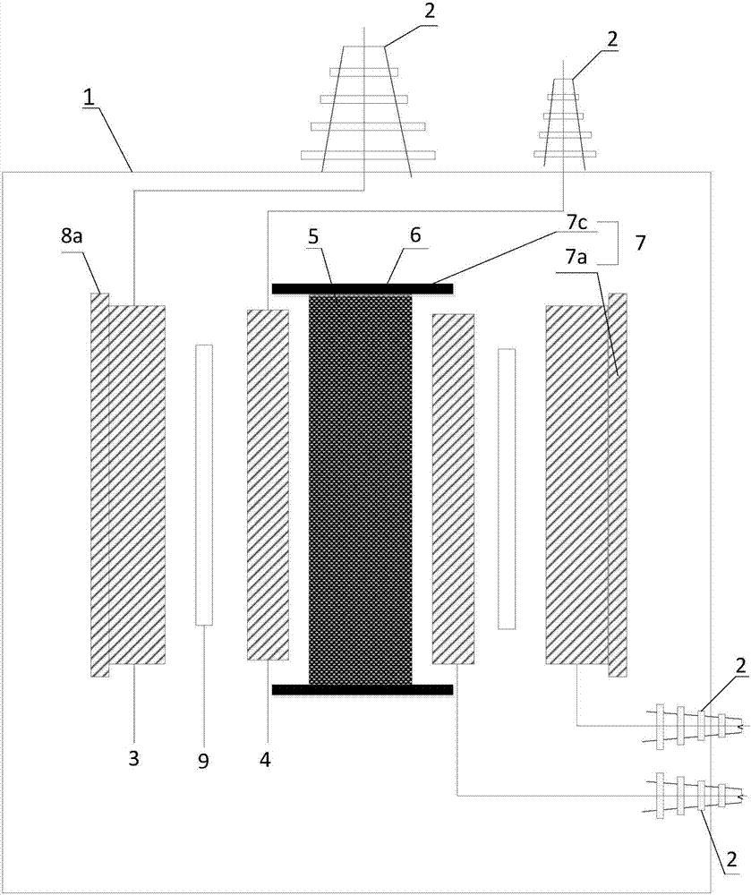
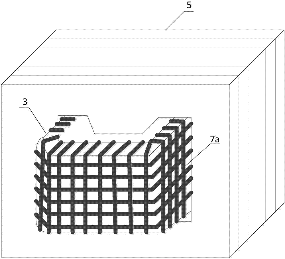
[0030] see figure 1 , figure 1 It is a schematic structural diagram of a distribution transformer based on glass fiber tape winding provided by an embodiment of the present invention. Depend on figure 1 It can be seen that the distribution transformer in the embodiment of the present invention mainly includes a casing 1, a lead bushing 2, an iron core 5, an iron core fastener 6, a high voltage winding 3, a low voltage winding 4, a glass fiber tape 7 and a plurality of bakelite rods 8 Eight components. Among them, the iron core fasteners 6 are arranged at both ends of the iron core 5, the low-voltage winding 4 and the high-voltage winding 3 are sequentially wound on the outside of the iron core 5 from inside to outside, and the iron core 5, the iron core fastener 6, and the high-voltage winding 3. The low-voltage winding 4, glass fiber tape 7 and multiple Bakelite rods 8 are arranged inside the casing 1, and the lead sleeve 2 is fixedly arranged on the casing.

[0031]The o...

Embodiment 2

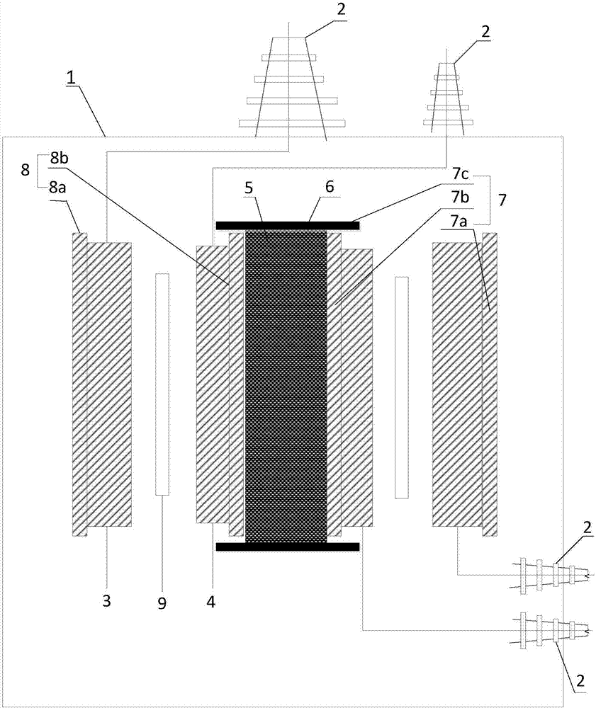
[0037] in the above figure 1 Based on the example shown see image 3 , image 3 A schematic structural diagram of another distribution transformer based on glass fiber tape winding provided by an embodiment of the present invention. Depend on image 3 It can be seen that a plurality of second bakelite rods 8b are evenly arranged between the outer surface of the iron core 5 and the inner surface of the low-voltage winding 4, and the second bakelite rods 8b are parallel to the central axis of the iron core 5, and the second bakelite rods 8b are parallel to the central axis of the iron core 5, and the second bakelite rods 8b are connected by winding the glass fiber tape 7b. The two glue sticks 8b and the low-voltage winding 4 are fixed together.

[0038] The second bakelite rod 8b is arranged between the iron core 5 and the low-voltage winding 4, which can avoid or reduce the deformation of the low-voltage winding due to the influence of electromotive force, thereby improving ...


PUM

PropertyMeasurementUnit
diameteraaaaaaaaaa

Abstract

The invention relates to a distribution transformer based on glass fiber tape winding. The distribution transformer comprises a housing, a lead sleeve, an iron core, an iron core fastener, a high-voltage winding and a low-voltage winding, wherein multiple insulating strips are arranged between the high-voltage winding and the low-voltage winding, multiple bakelite rods are evenly arranged on the outer surface of the high-voltage winding, the bakelite rods are parallel to the central axis of the iron core, and the bakelite rods and the high-voltage winding are fixed together by winding a glass fiber tape. The surrounding of the connecting position of the iron core and the iron core fastener is tightly wound with a glass fiber tape. By arranging the glass fiber tape outside the high-voltage winding, the phenomenon that the performance of the distribution transformer is affected by winding expansion or contraction can be effectively avoided. By arranging the bakelite rods, deformation of the winding in the horizontal direction can be effectively inhibited, and by arranging the glass fiber tape at the connecting position of the iron core and the iron core fastener, rotary displacement of the iron core can be effectively avoided. The operating stability of the distribution transformer can be greatly improved, and the distribution transformer is simple in structure, high in practicability and convenient to popularize and use.

Description

technical field [0001] The invention relates to the technical field of transformer preparation technology, in particular to a distribution transformer based on glass fiber tape winding. Background technique [0002] The distribution transformer is a static electrical device that transmits AC power by transforming AC voltage and current according to the law of electromagnetic induction in the power distribution system. From the perspective of transformer capacity and voltage level, distribution transformers usually refer to power transformers that operate in the distribution network with a voltage level of 10-35kV, a capacity of 6300kVA and below, a secondary voltage of 400V, and directly supply power to end users. . Distribution transformers are widely used in industrial and mining enterprises, urban streets, residential areas and remote villages. Due to the wide range of applications of distribution transformers, in the field of transformer preparation technology, the str...

Claims


Application Information

Patent Timeline
Patent Type & Authority Applications(China)
IPC IPC(8): H01F27/26H01F27/30H01F27/32
CPCH01F27/263H01F27/303H01F27/324
Inventor 刘光祺杨航谢乐刘凌唐凌霄王科刘轩东钱国超邹徳旭颜冰
Owner YUNNAN POWER GRID CO LTD ELECTRIC POWER RES INST
Learn More