
Irradiation apparatus

A technology of equipment and light quantity, which is applied in the direction of lighting devices, fixed lighting devices, lighting and heating equipment, etc., and can solve problems such as undifferentiated irradiation

Inactive Publication Date: 2012-07-25
PANASONIC INTELLECTUAL PROPERTY MANAGEMENT CO LTD
View PDF7 Cites 1 Cited by
  • Summary
  • Abstract
  • Description
  • Claims
  • Application Information

AI Technical Summary

Problems solved by technology

[0008] However, there is a problem: the setting of light quantity or light color is carried out for the light distribution of the whole room, but does not differentiate the lighting for the overall atmosphere of the room, or the ceiling surface, wall surface, floor and other parts of the room.

Method used


Image

  • Irradiation apparatus
  • Irradiation apparatus
  • Irradiation apparatus

Examples


no. 1 Embodiment approach

[0042] Hereinafter, an irradiation device according to a first embodiment of the present invention will be described using the drawings.

[0043] In addition, in the following description, the case where an irradiation tool is attached to the surface to be attached and irradiates to the lower space side is demonstrated.

[0044] Therefore, unless otherwise indicated, upper (upper space side, upper side, etc.) means the ceiling surface side, and lower (lower space side, lower side, etc.) means the ground side.

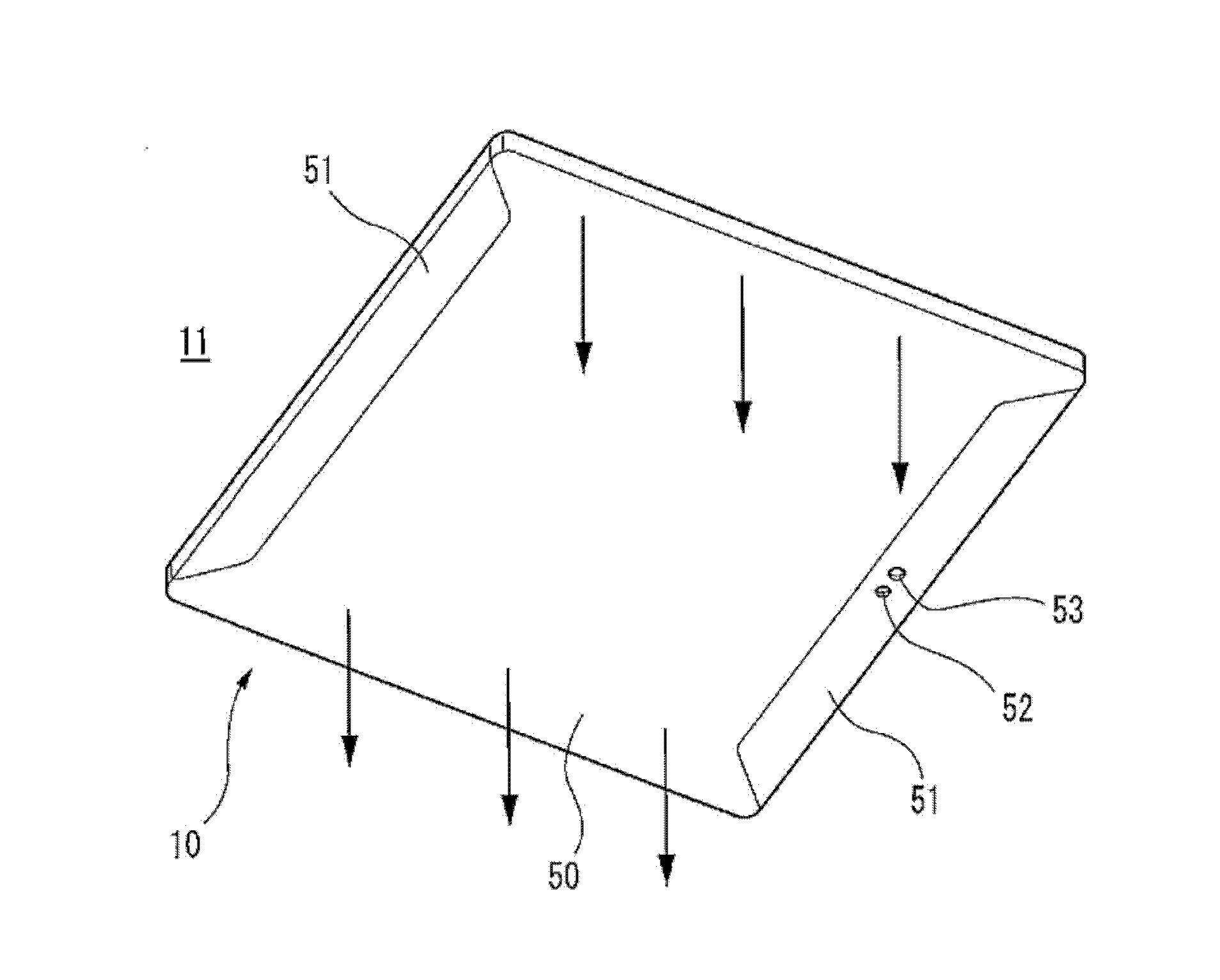
[0045] Such as figure 1 As shown, the irradiation device 10 according to the first embodiment of the present invention is suitable for being installed on the ceiling surface 11 or the like as an installation surface, and mainly irradiates the lower space side.

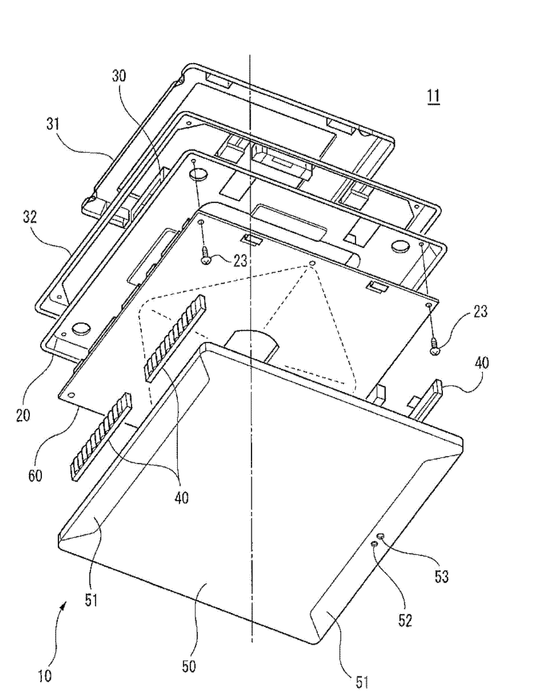
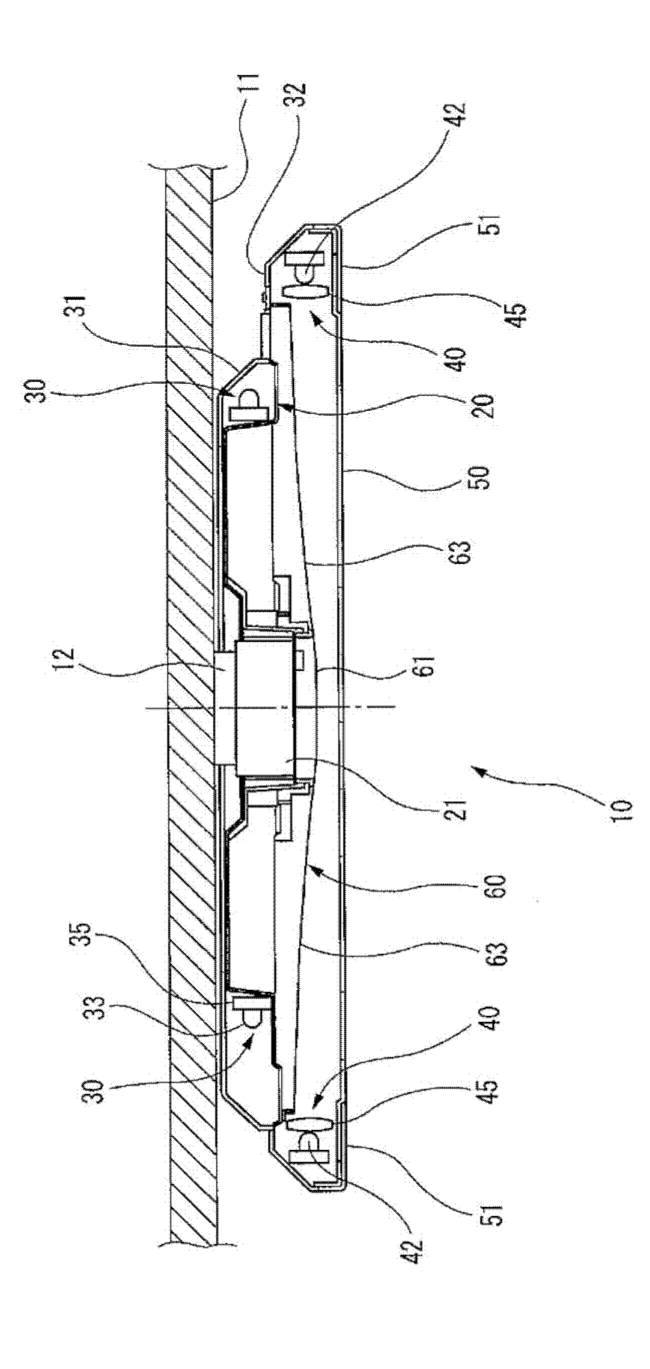
[0046] Such as figure 2 and image 3 As shown, the irradiation equipment 10 has, for example, a square plate-shaped equipment main body 20, and has an installation fitting 21 for installation to a ceiling s...


PUM

PropertyMeasurementUnit
Thermal conductivityaaaaaaaaaa

Abstract

The invention provides an irradiation apparatus, wherein the atmosphere of a room is controlled through the control mode of a plurality of light sources. A control part (62) controls a lower unit (40) and an upper unit (30), wherein a first mode with a certain light quantity and a variable light color, a second mode with a variable light quantity and a certain light color and a third mode with a variable light quantity and a variable light color can be chosen. Meanwhile, the control part can respectively and simultaneously adjust the light quantities of both the upper unit (30) and the lower unit (40) through adjusting the output ratio. Therefore, the control part (62) can choose among the first mode, the second mode and the third mode and can easily change the demonstration effect or the atmosphere within a room.

Description

technical field [0001] The present invention relates to an irradiation device that uses an LED (Light Emitting Diode) as a light source, is mainly installed on a ceiling surface, and irradiates the lower space side. Background technique [0002] Conventionally, an irradiating device that uses LEDs as a light source, is mounted on a ceiling surface, and irradiates the space below is known (for example, refer to Patent Document 1). [0003] Such as Figure 27 As shown, the irradiation device 100 described in Patent Document 1 has a device main body 103 suspended and supported from a ceiling surface 101 through wires 102 . A plurality of LEDs 104 that irradiate light toward the lower space side are respectively attached to the bottom surface of the instrument main body 103 . The instrument main body 103 is octagonal when viewed from above, each side is made of a light-transmitting material such as acrylic resin, and a light guide 105 optically coupled to an LED 104 as a light ...

Claims


Application Information

Patent Timeline
IPC IPC(8): F21S8/04F21V19/00F21Y101/02
Inventor 前田光小林浩明速水拓上本泰生
Owner PANASONIC INTELLECTUAL PROPERTY MANAGEMENT CO LTD
Features
  • Generate Ideas
  • Intellectual Property
  • Life Sciences
  • Materials
  • Tech Scout
  • Unparalleled Data Quality
  • Higher Quality Content
  • 60% Fewer Hallucinations
Learn More