Three-Dimensional Display with Motion Parallax

A motion parallax and parallax technology, applied in image communication, equipment, stereo system, etc., can solve problems such as fatigue and discomfort

Inactive Publication Date: 2012-07-25
MICROSOFT TECH LICENSING LLC
View PDF9 Cites 32 Cited by
  • Summary
  • Abstract
  • Description
  • Claims
  • Application Information

AI Technical Summary

Problems solved by technology

This resistance causes some viewers to experience fati

Method used


Image

  • Three-Dimensional Display with Motion Parallax
  • Three-Dimensional Display with Motion Parallax
  • Three-Dimensional Display with Motion Parallax

Examples


Embodiment Construction

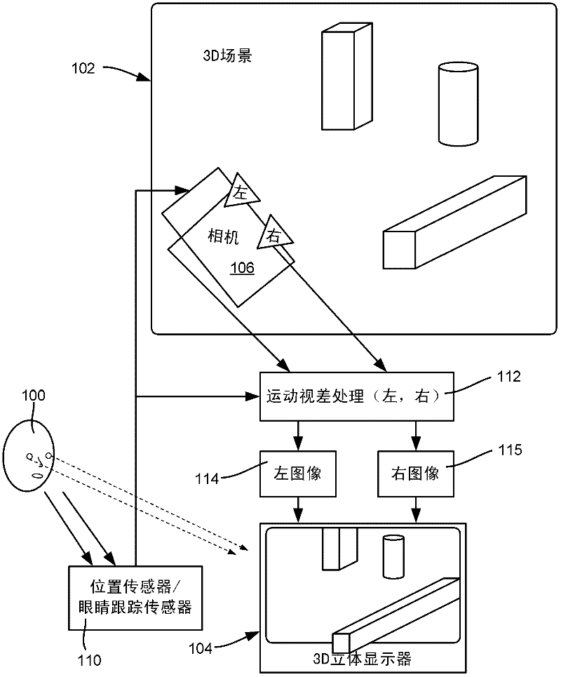
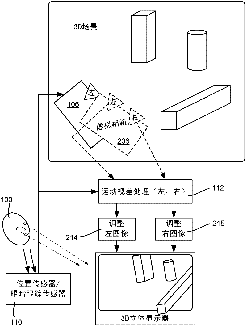
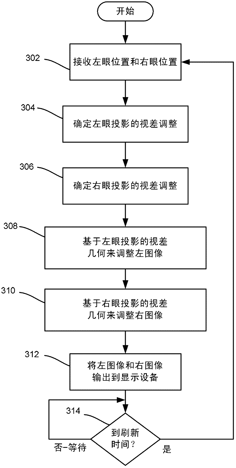
[0018] Aspects of the invention generally relate to a hybrid stereoscopic image / motion parallax system that uses stereoscopic 3D vision technology to present a different image to each eye, combined with motion parallax technology to adjust the left and right images for the position of the viewer's eyes . In this way, the viewer receives both stereoscopic and parallax cues as the viewer moves while viewing the 3D scene, which tends to result in greater visual comfort / less fatigue for the viewer. To this end, the position of each eye (or eyeglass lens, as described below) can be tracked directly or via estimation. A 3D image of the scene is presented to each eye in real time using perspective projection computed from the viewer's point of view, providing parallax cues.

[0019] It should be understood that any examples herein are non-limiting. Thus, the invention is not limited to any specific embodiment, aspect, concept, structure, function or example described herein. Rathe...


PUM


Abstract

The subject disclosure is directed towards a hybrid stereo image/motion parallax system that uses stereo 3D vision technology for presenting different images to each eye of a viewer, in combination with motion parallax technology to adjust each image for the positions of a viewer's eyes. In this way, the viewer receives both stereo cues and parallax cues as the viewer moves while viewing a 3D scene, which tends to result in greater visual comfort/less fatigue to the viewer. Also described is the use of goggles for tracking viewer position, including training a computer vision algorithm to recognize goggles instead of only heads/eyes.

Description

technical field [0001] The present invention relates to three-dimensional displays. Background technique [0002] The human brain gets its three-dimensional (3D) cues in various ways. One of these ways is via stereopsis, which corresponds to the difference between the viewed images presented to the left and right eyes. Another way is through motion parallax, which corresponds to the way a viewer sees a scene that changes as the viewing angle changes, such as when the viewer's head moves. [0003] Current 3D displays are based on stereo vision. In general, 3D televisions and other displays output separate frames of video to each eye via 3D glasses or glasses that have lenses that block certain frames and let others pass through. Examples include using different colors for left and right images with glasses with corresponding filters, using light polarization and corresponding different polarizations for left and right images, and using shutters in glasses. The brain assem...

Claims


Application Information

Patent Timeline
IPC IPC(8): H04N13/04H04N13/239
CPCH04N13/0481H04N13/0468H04N13/0479H04N13/0022H04N13/0296H04N13/0278H04N13/0033H04N13/0239H04N13/0014H04N13/0477H04N13/378H04N13/279H04N13/376H04N13/38H04N13/296H04N13/144H04N13/366H04N13/239H04N13/128G02B30/00
Inventor C·休特玛E·莱恩E·萨尔尼科夫
Owner MICROSOFT TECH LICENSING LLC
Why Eureka
Try Eureka