
High-speed flywheel battery rotor

A flywheel battery, high-speed technology, applied in the direction of electrical components, electromechanical devices, electric components, etc., to achieve the effect of weakening the tearing of the inner and outer edges

Inactive Publication Date: 2014-03-19
深圳飞能能源有限公司
View PDF8 Cites 0 Cited by
  • Summary
  • Abstract
  • Description
  • Claims
  • Application Information

AI Technical Summary

Problems solved by technology

[0016] The technical problem to be solved by the present invention is to overcome the deficiencies of the above-mentioned prior art, and provide a rotor for a high-speed flywheel battery, which adopts a segmented arc-shaped hub structure, which cleverly avoids the problems of loose hubs or insufficient strength of the hubs. At the same time, the hub itself can also press the inner wall of the cylinder to make it expand outward, so that the expansion of the outer and inner edges of the cylinder tends to be consistent, thus weakening the tearing of the inner and outer edges of the cylindrical rotor at high speed

Method used


Image

  • High-speed flywheel battery rotor
  • High-speed flywheel battery rotor
  • High-speed flywheel battery rotor

Examples


Embodiment Construction

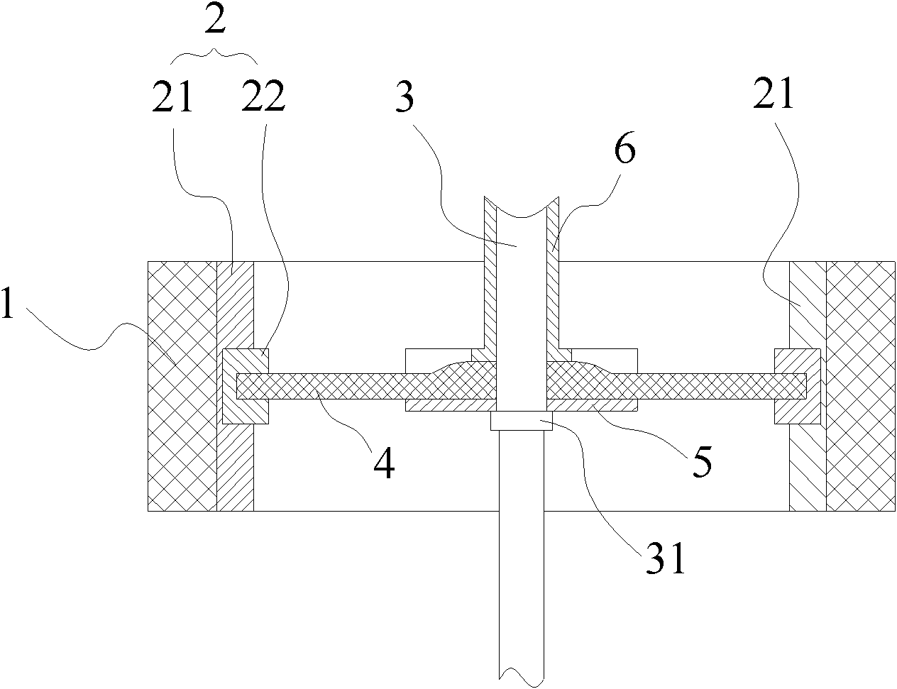
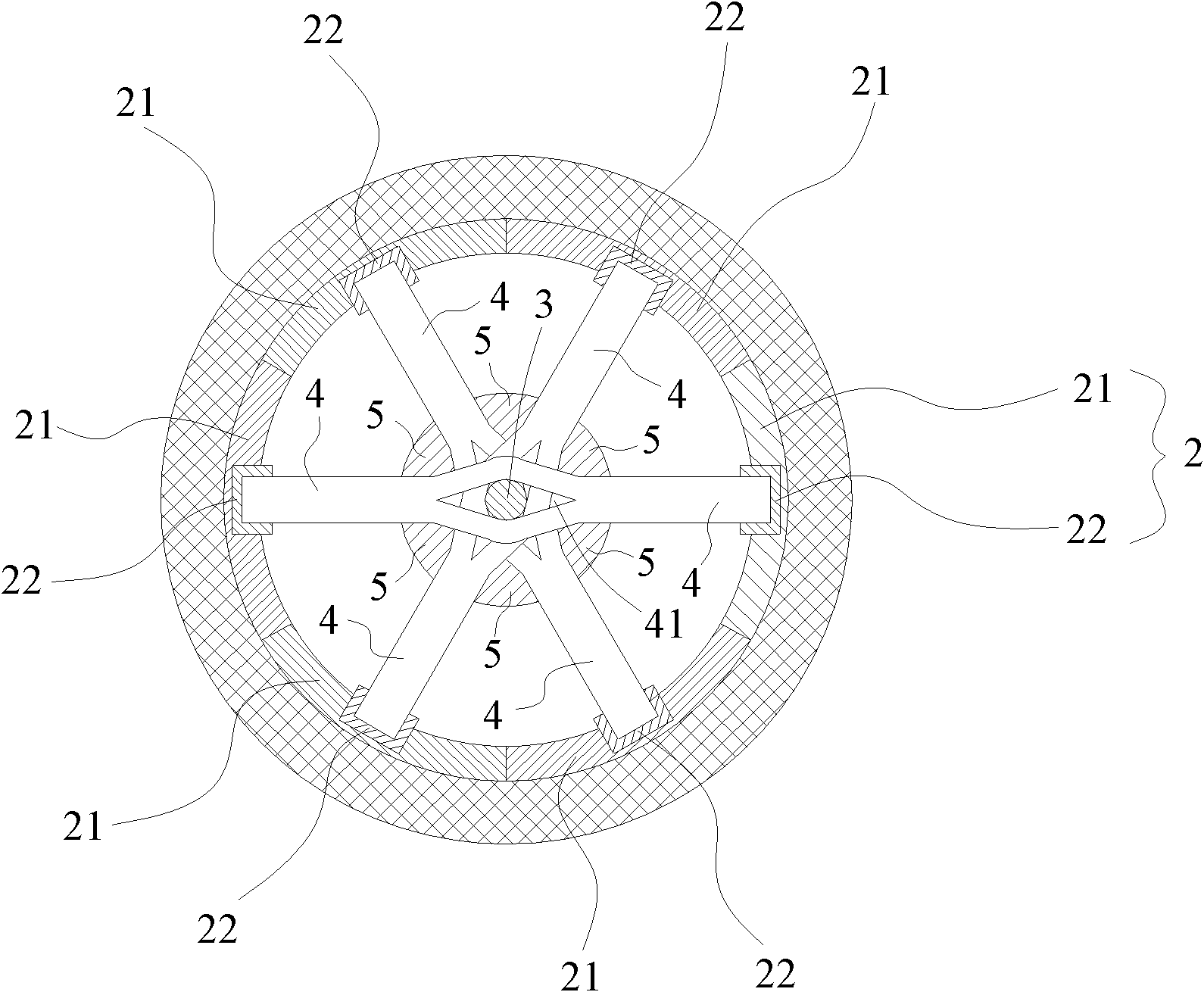
[0032] refer to figure 2 , image 3 , The rotor of the high-speed flywheel battery of the present invention includes: a cylinder 1 of high-strength composite material, a hub 2 set in the cylinder 1, and a rotating shaft 3 that drives the hub 2 to rotate. The hub 2 is assembled by a plurality of arc plates 21. On the shaft 3, there are a plurality of shaft bars 4 connected to the shaft 3 and distributed radially along the hub 2. Each arc plate 21 and the free end of each shaft bar 4 are matched The radial interference fit of the parts on the hub.

[0033] The fitting can be a shaft sleeve that is connected on the arc plate 21 and protrudes radially inward along the arc plate 21, or can be figure 2 , image 3 As shown in the figure, a groove is established in the middle part of the arc plate 21, and then an axle sleeve 22 is established in the groove, so that the free ends of each axle bar 4 are respectively inserted in the axle sleeve 22 of each arc plate 21 and It is int...


PUM


Abstract

A high-speed flywheel battery rotor includes a high-strength composite material cylinder, a wheel hub sheathed in the cylinder and a spindle for driving the rotation of the wheel hub: the wheel hub being formed by spliced multiple sections of arc plates, a plurality of shafts connected to the spindle and distributed along the radical direction of the wheel hub, being disposed on the spindle, a groove being disposed in the center part of each arc plate, a shaft sleeve being disposed in each groove, and a free end of each shaft being inserted in the shaft sleeve of each arc plate and being in interference fit with the shaft sleeve in the radial direction of the wheel hub. By adopting the segmented arc wheel hub structure, the high-speed flywheel battery rotor cleverly avoids the problems of the insufficient strength and the loosening of the wheel hub, and at the same time, the wheel hub can also press the inner wall of the cylinder to make the cylinder expand outward so as to make the inward expansion volume and the outward expansion volume of the cylinder tend to be consistent, decreasing the phenomenon of inward and outward tearing when the cylinder rotor is under high speed.

Description

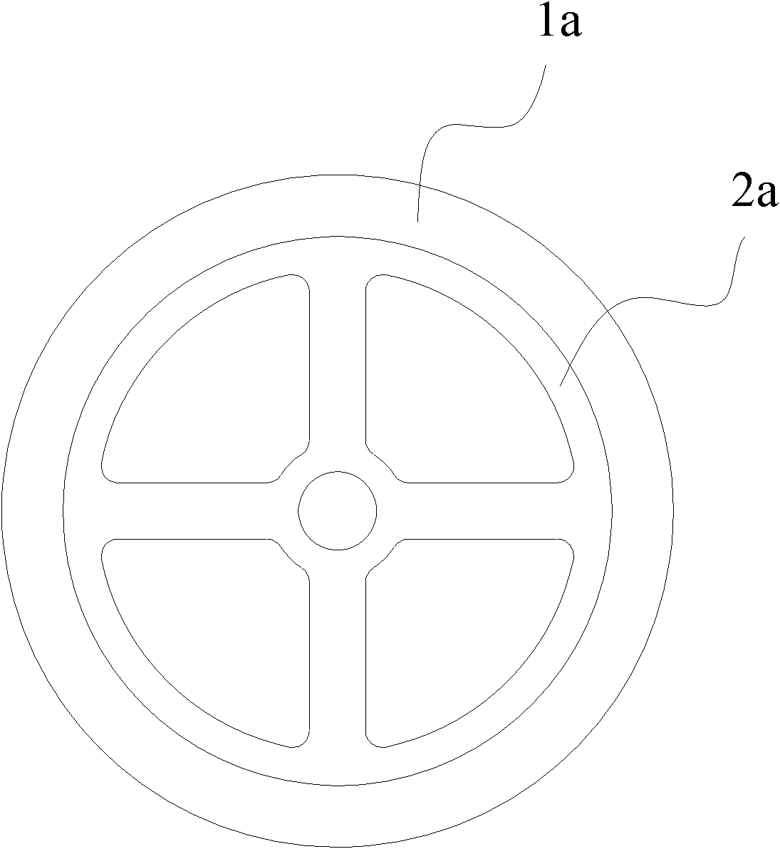
technical field [0001] The invention relates to the field of high-speed flywheel batteries, in particular to the rotor structure of high-speed flywheel batteries. Background technique [0002] refer to figure 1 A high-speed flywheel battery (flywheel energy storage system) usually includes a cylinder 1a of high-strength composite material and a metal hub 2a set in the cylinder 1a, and the metal hub 2a drives the cylinder 1a to accelerate or decelerate. Since the metal hub 2a is inside the cylinder 1a, its outer linear velocity is smaller than that of the cylinder 1a, so the centrifugal force and stress on the hub 2a are also smaller than those on the cylinder 1a, while the metal hub 2a The elastic modulus is generally larger than that of the composite material, so when rotating at high speed, the expansion of the composite material cylinder 1a is larger than that of the metal hub 2a, resulting in the cylinder 1a and the hub 2a getting loose. Torque can no longer be transmi...

Claims


Application Information

Patent Timeline
Patent Type & Authority Patents(China)
IPC IPC(8): H02K7/02H02K1/22
CPCY02E60/16
Inventor 肖耀军
Owner 深圳飞能能源有限公司
Learn More