
High-speed motor

A technology of high-speed motors and vacuum machines, which is applied in the direction of electrical components, electromechanical devices, magnetic circuit static parts, etc., can solve the problem that the motor speed cannot be increased, and achieve the effect of weakening the cracking phenomenon of the inner and outer layers

Inactive Publication Date: 2013-12-04
深圳飞能能源有限公司
View PDF7 Cites 0 Cited by
  • Summary
  • Abstract
  • Description
  • Claims
  • Application Information

AI Technical Summary

Problems solved by technology

[0013] The technical problem to be solved by the present invention is to overcome the deficiencies in the above-mentioned prior art and provide a high-speed motor to solve the defect that the motor speed cannot be increased due to various reasons in the prior art

Method used


Image

  • High-speed motor
  • High-speed motor
  • High-speed motor

Examples


Embodiment Construction

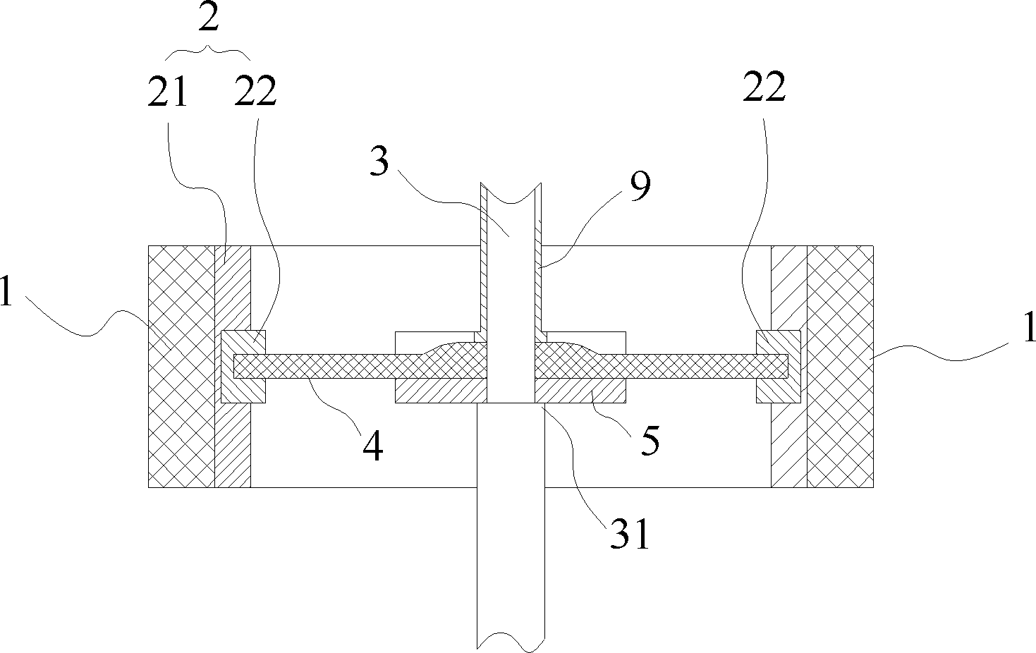
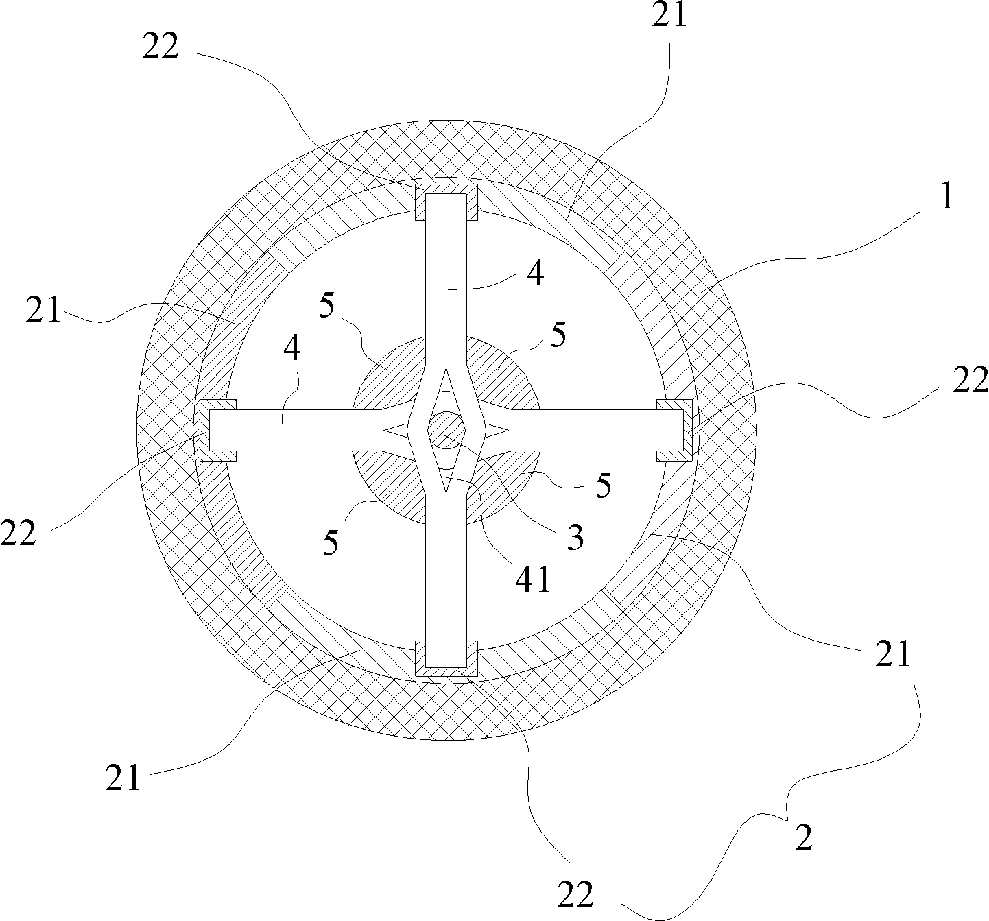
[0036] refer to figure 1 , figure 2, The rotor of the high-speed motor of the present invention includes: a cylinder 1 , a hub 2 set in the cylinder 1 , a shaft bar 4 connected to the hub 2 and a rotating shaft 3 . The cylinder 1 is made of high-strength fiber composite material, the hub 2 is made of metal, and the cylinder 1 is sleeved on the outer wall of the hub 2 to help the hub 2 bear centrifugal force. The hub 2 is assembled by a plurality of circular arc plates 21, and an axle sleeve 22 is arranged on the inner wall of each arc plate 21. The axle bars 4 are connected to the rotating shaft 3 and distributed radially along the hub 2. The freedom of each axle bar 4 The ends are respectively inserted in the shaft sleeves 22 of the circular arc plates 21 and are interference-fitted with the shaft sleeves 22 in the radial direction of the hub 2 .

[0037] The shaft sleeve 22 can be protrudingly arranged on the inner wall of the arc plate 21 , and can also be embedded in th...


PUM


Abstract

A high-speed motor includes a stator and a rotor disposed in a vacuum motor shell, the rotor being arranged outside the stator, wherein the rotor includes: a cylinder, a wheel hub sheathed in the cylinder, a plurality of shafts connected to the wheel hub and a spindle, the wheel hub being formed by spliced multiple sections of arc plates, a shaft sleeve being disposed on the inner wall of each arc plate, and a free end of each shaft being inserted in the shaft sleeve of each arc plate and being in interference fit with the shaft sleeve in the radial direction of the wheel hub. The high-speed motor is provided with high revolving speed, and is free from the problems of the insufficient strength as well as the loosening and dropping of the wheel hub, and at the same time, the wheel hub can also press the inner layer of the cylinder to make the cylinder expand outward so that the expansion volume of the outer layer and the inner layer of the cylinder tends to be consistent, weakening the phenomenon of internal and external layer cracking when the cylinder is under high speed.

Description

technical field [0001] The present invention relates to high-speed electric machines, and in particular to the construction of the rotor portion of high-speed electric machines. Background technique [0002] The centrifugal force suffered by the rotating object is proportional to the weight of the rotating object, the square of the angular velocity of rotation and the radius of rotation. Due to the limitation of material strength, if a high-speed motor wants to achieve a higher angular velocity of rotation, it has to reduce the radius of rotation, thereby reducing the centrifugal force . However, the reduction of the radius of rotation will inevitably lead to the reduction of the space between the rotor and the stator of the motor, so that more magnets and wires cannot be arranged, which makes it difficult to increase the power of the high-speed motor. [0003] The motor requires both high speed and high power. Generally, there are two not-so-good solutions: [0004] 1. Th...

Claims


Application Information

Patent Timeline
Patent Type & Authority Patents(China)
IPC IPC(8): H02K1/22H02K1/17H02K16/04
Inventor 肖耀军李方
Owner 深圳飞能能源有限公司
Learn More