Cooling structure and manufacturing method thereof

A technology of heat dissipation structure and manufacturing method, which is applied in the direction of cooling/ventilation/heating transformation, etc., which can solve the problems of material damage, high production cost, spillage, etc., and achieve the effect of preventing leakage and saving material cost

Inactive Publication Date: 2012-08-01
ASIA VITAL COMPONENTS SHENZHEN CO LTD
View PDF5 Cites 4 Cited by
  • Summary
  • Abstract
  • Description
  • Claims
  • Application Information

AI Technical Summary

Problems solved by technology

[0007] Furthermore, since the material itself of the water-cooled head may be damaged due to oxidation or deterioration after a period of use, causing the heat-dissipating fluid to leak outward in the water channel, it is a very serious problem for the electronic equipment used in conjunction with it. The destruction of; Therefore prior art has following shortcoming:
[0008] 1. It is easy to cause leakage;
[0009] 2. High production cost

Method used


Image

  • Cooling structure and manufacturing method thereof
  • Cooling structure and manufacturing method thereof
  • Cooling structure and manufacturing method thereof

Examples


Embodiment Construction

[0062] The above-mentioned purpose of the present invention and its structural and functional characteristics will be described according to the preferred embodiments of the accompanying drawings.

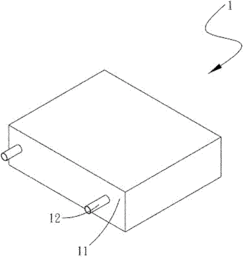
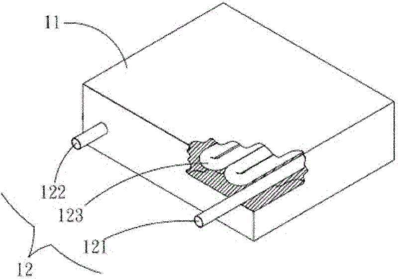
[0063] see figure 1 , 2 , is a perspective view and an exploded view of the first embodiment of the heat dissipation structure of the present invention. As shown in the figure, the heat dissipation structure includes: a base 1; the base 1 has a body 11 and at least one tube body 12, so The pipe body 12 has an inlet end 121 , an outlet end 122 and a pipe body 123 , the pipe body 123 is correspondingly disposed in the body 11 , and the outlet end 122 and the inlet end 121 protrude outside the body 11 .

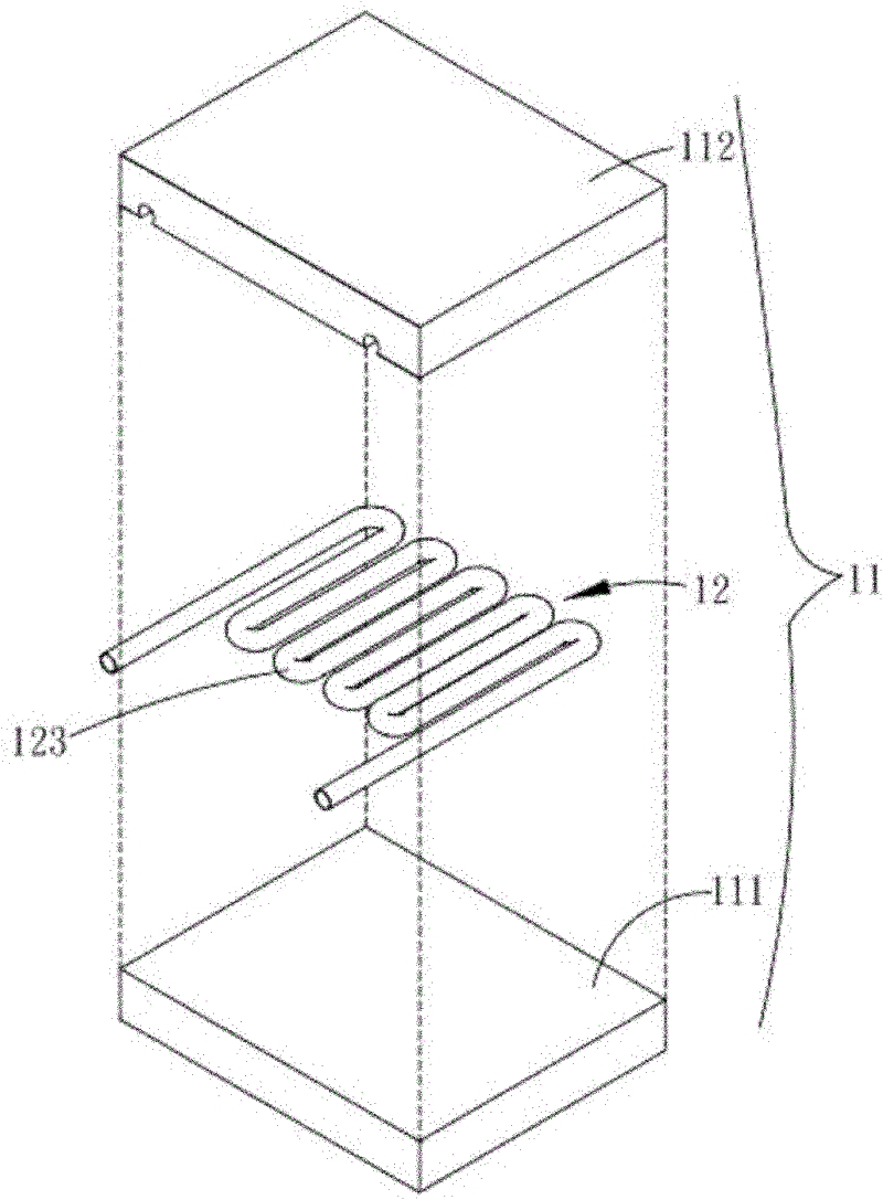
[0064] see image 3 , is a three-dimensional exploded view of the second embodiment of the heat dissipation structure of the present invention. As shown in the figure, part of the structure of this embodiment is the same as that of the aforementioned first embodiment, so it will no...


PUM


Abstract

The invention relates to a cooling structure and a manufacturing method thereof, wherein the cooling structure comprises a substrate. The substrate includes a body and at least one pipe body, wherein the pipe body comprises an inlet end, an outlet end, and a pipe body portion. The pipe body portion is correspondingly arranged in the body, while the outlet end and the inlet end projectingly extend out of the body. A waterway is formed by injecting a body package of the pipe body into the internal part of the substrate, which not only reduces the cost, but also prevents the occurrence of waterway leakage.

Description

technical field [0001] A heat dissipation structure and its manufacturing method, especially a method of pouring a single or multiple materials, covering at least one tube body to form a base, and the tube body forms a water channel inside the base, so as to A heat dissipation structure and a manufacturing method thereof for cost saving and leakage prevention. Background technique [0002] As the computing performance of electronic equipment increases day by day, the electronic components installed inside it will generate a lot of heat during operation. It is usually necessary to install radiators or cooling fins on the electronic components to increase the heat dissipation area and improve the heat dissipation effect. However, radiators and The heat dissipation fins only dissipate heat through radiation, and the heat dissipation effect achieved is limited. Therefore, a large number of liquid-cooled heat dissipation modules are used in the prior art as a solution to enhance ...

Claims


Application Information

Patent Timeline
Patent Type & Authority Applications(China)
IPC IPC(8): H05K7/20B22D19/08
Inventor 李嵩蔚高百龄
Owner ASIA VITAL COMPONENTS SHENZHEN CO LTD
Why Eureka
Try Eureka