Dynamoelectric machine

A machine and electromechanical technology, applied in the field of electromechanical machines, can solve problems such as insufficient cooling

Active Publication Date: 2012-08-01
VOITH PATENT GMBH
View PDF5 Cites 0 Cited by
  • Summary
  • Abstract
  • Description
  • Claims
  • Application Information

AI Technical Summary

Problems solved by technology

Such insufficient cooling

Method used


Image

  • Dynamoelectric machine
  • Dynamoelectric machine
  • Dynamoelectric machine

Examples


Embodiment Construction

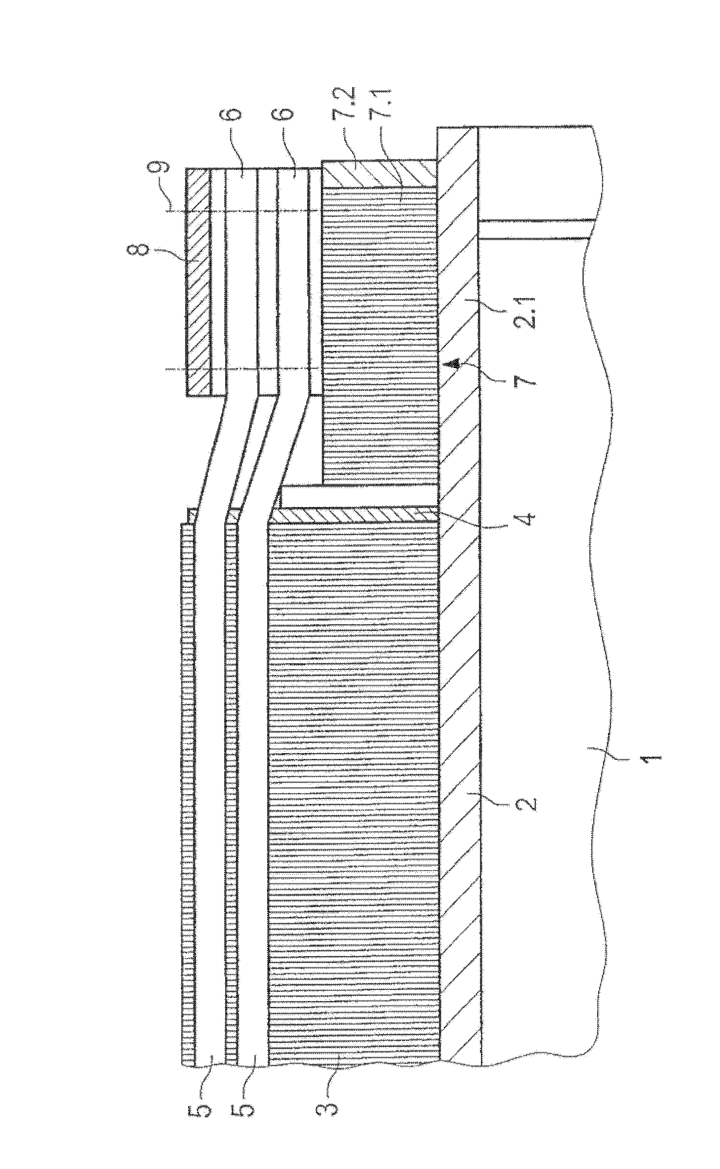
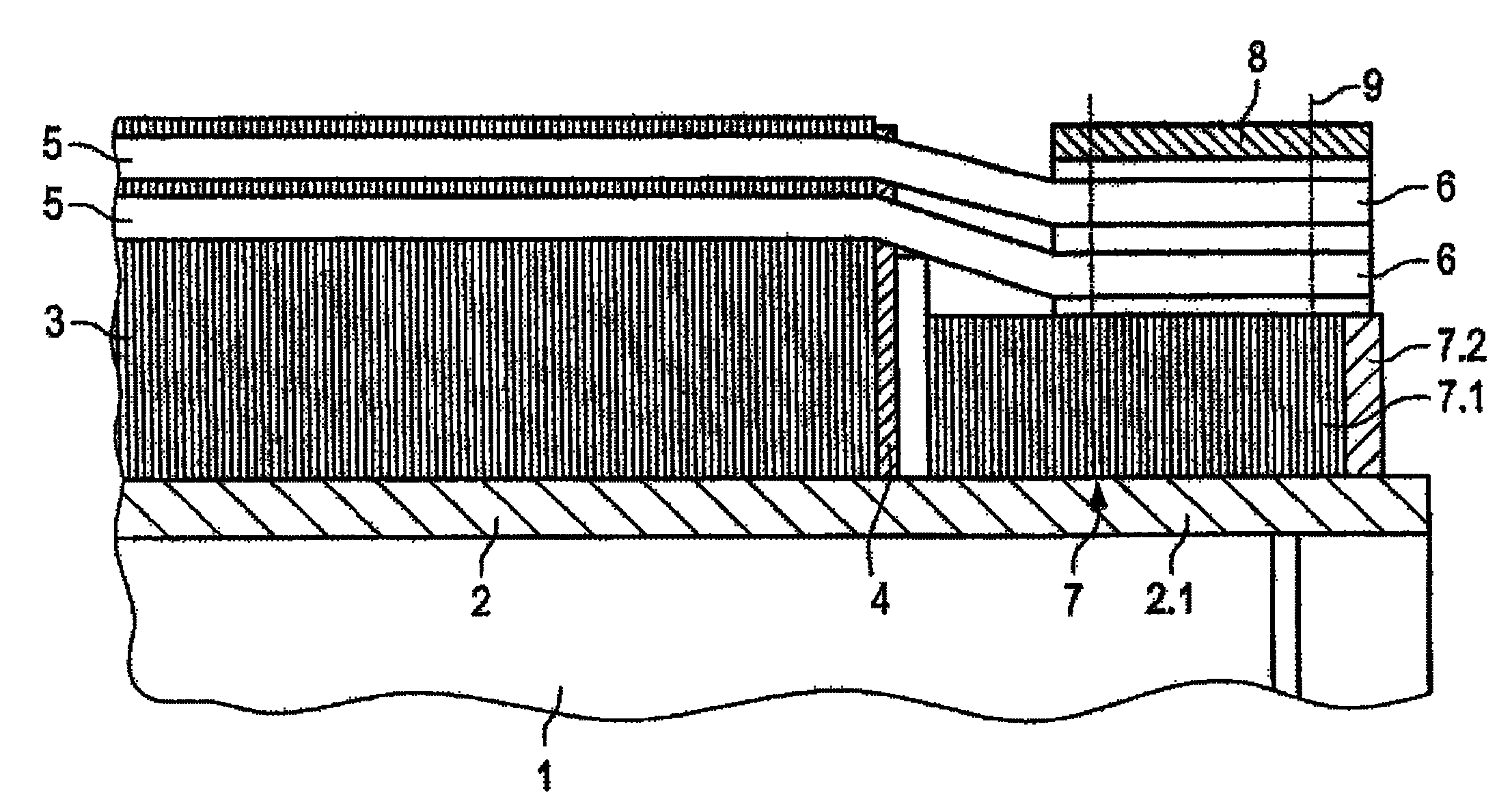
[0014] figure 1 Rotor 1 of the electromechanical machine is shown. The rotor has an outer diameter of several meters, for example 5 meters or 6 meters. The shaft part 2 carries a laminated rotor core 3 . The shaft part 2 is clamped axially by means of a pressure plate 4 . The windings 5 ​​are placed in the grooves of the laminate of the rotor. Windings 5 ​​and winding heads 6 protrude axially from rotor core 3 .

[0015] The shaft portion is axially extended by the shaft extension 2.1 to support the winding head 6. The shaft extension 2.1 carries the further laminated magnetic core body 7 as well as the laminate 7.1 and the pressure plate 7.2. The winding head is further surrounded by an annular support 8 . A plurality of bending rigid plate-like annular portions are included. The tensioning bolt 9 serves to clamp the support body 8 and the core 7 of the shaft extension 2.1.

[0016] DE 19519127 C1 describes such an embodiment.

[0017] According to the present invent...


PUM


Abstract

The invention relates to a dynamoelectric machine comprising the following components or features: a rotor body (10); annular coil heads (60) which are arranged axially next to the rotor body (10) and in a coaxial relation thereto; a supporting ring (30) which is arranged radially inside the coil heads (60) and in a coaxial relation thereto; the coil heads (60) and the supporting ring (30) are non-rotatable relative to the rotor body (10); and the coil heads (60) and the supporting ring (30) are radially braced with each other by tension bars (90) which extend through radial bores (30.2) in the coil heads (60) and in the supporting ring (30). The invention is characterized by the following features: the tension bars (90) act upon the supporting ring (30) with their radially inner ends, and upon bearing elements (80) with their radially outer ends, the bearing elements resting against the coil heads (60); the diameters inside the radial bores (30.2) in the supporting ring (30) are overdimensioned relative to the diameters of the tension bars (90); the bearing of the radially inner ends of the tension bars (90) on the supporting ring (30) and the radially outer ends of the tension bars (90) on the coil heads (60) allow the tension bars (90) to be tilted to a limited extent with respect to the radial direction.

Description

technical field [0001] The invention relates to a dynamoelektrische maschine, such as a generator. The invention concerns in particular a structural arrangement of a design with which the winding head of the rotor can be protected against centrifugal forces. [0002] This electromechanical machine comprises the following components: a main rotor; an annular winding head arranged close to and coaxially with the main rotor; a support ring arranged radially inward of the winding head And it is coaxial with the winding head. Background technique [0003] In order to fasten the winding head of the rotor winding, the conventional method is to support the winding head inside by means of an annular winding support and fasten the winding head on the winding support by means of winding. Especially in the case of large machines, it is possible to replace the winding with multiple spacer rings which rest on the winding head via an insulating interlayer and which are screwed to the win...

Claims


Application Information

Patent Timeline
IPC IPC(8): H02K3/51
CPCH02K3/51
Inventor 霍尔格·亨宁菲利普·艾勒布雷希特斯特凡·威瑟托马斯·希尔丁格
Owner VOITH PATENT GMBH
Why Eureka
Try Eureka