Supercharge Your Innovation With Domain-Expert AI Agents!

Preshrinking machine for knitted blanket

A pre-shrinking machine and woolen blanket technology, which is applied in textile processing machine accessories, shrinking, textiles and papermaking, etc., can solve the problems that the shrinking effect is not very good, and the production efficiency of fabrics is difficult to improve, so as to improve the pre-shrinking effect Effect

Inactive Publication Date: 2012-08-15
JIANGYIN FUDA DYEING & FINISHING UNITED MACHINERYCO
View PDF2 Cites 6 Cited by
  • Summary
  • Abstract
  • Description
  • Claims
  • Application Information

AI Technical Summary

Problems solved by technology

[0002] At present, the knitting pre-shrinking machine is used for pre-shrinking the fabric, including the cloth input frame, the electromechanical centering device, the needle rail device, the cloth output frame and the steam tank. , The cloth outlet frame is connected in sequence, the steam tank is set under the needle rail device; the needle rail device includes the frame, the cloth inlet roller, the cloth feed roller, the needle rail, the cloth outlet roller and the cooling roller, and the needle rail is installed on the frame. The cloth entry roller is installed on the frame under the front and bottom of the needle rail, the cloth feeding roller is installed on the frame above the front and upper part of the needle rail, the cloth outlet roller is installed on the frame above the rear of the needle rail, and the cooling roller is installed behind the cloth outlet roller On the frame above; the existing knitting pre-shrinking machine only pre-wets the fabric on the needle rail device through the steam sprayed from the steam tank to make the fabric shrink, because the spray on the fabric will not be very uniform , the shrinking effect of the fabric is not very good, and it is often necessary to pre-shrink twice on the knitting pre-shrinking machine to completely shrink the effect, so the production efficiency of the fabric is difficult to improve

Method used


Image

  • Preshrinking machine for knitted blanket
  • Preshrinking machine for knitted blanket

Examples


Embodiment Construction

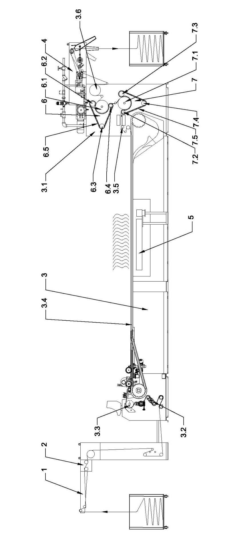
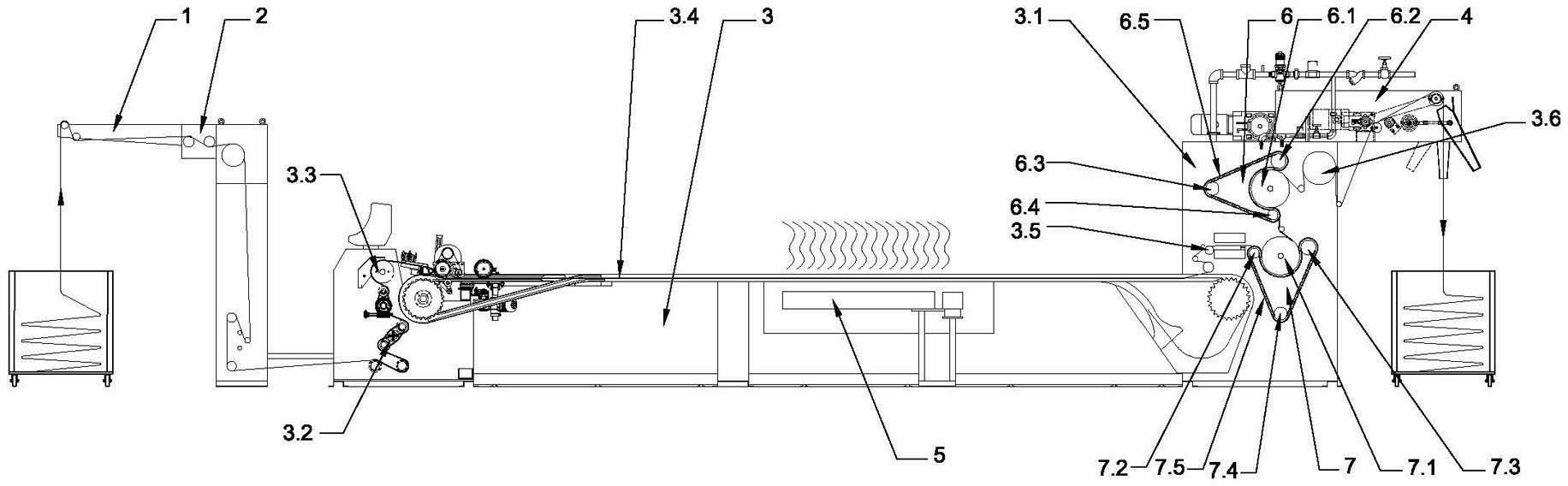
[0007] like figure 1 As shown, the knitted wool blanket pre-shrinking machine includes a cloth input frame 1, an electromechanical centering device 2, a needle rail device 3, a cloth output frame 4 and a steam tank 5, wherein the needle rail device 3 includes a frame 3.1, a cloth input roller 3.2, Feeding roller 3.3, needle rail 3.4, cloth outlet roller 3.5 and cooling roller 3.6; it is characterized in that the needle rail device 3 also includes an upper blanket finishing device 6 and a lower blanket finishing device 7; the upper blanket finishing device 6 includes an upper blanket driving roller 6.1 , upper blanket upper roller 6.2, upper blanket forward roller 6.3, upper blanket lower roller 6.4 and upper blanket 6.5, upper blanket upper roller 6.2, upper blanket forward roller 6.3 and upper blanket lower roller 6.4 respectively arranged on the upper Above, in front of and below the blanket driving roller 6.1, the upper felt 6.5 is set on the upper blanket turning roller 6....


PUM


Abstract

The invention relates to a preshrinking machine for a knitted blanket. The preshrinking machine comprises a cloth inlet frame, an electromechanical centring device, a needle track device, a cloth outlet frame and a steam groove, wherein the needle track device comprises a rack, a cloth inlet roller, a cloth feeding roller, a needle track, a cloth outlet roller and a cooling roller; the needle track device further comprises an upper blanket finishing device and a lower blanket finishing device; the upper blanket finishing device comprises an upper blanket driving roller, an upper blanket upper turning roller, an upper blanket front turning roller, an upper blanket lower turning roller and an upper blanket; the lower blanket finishing device comprises a lower blanket driving roller, a lower blanket front turning roller, a lower blanket rear turning roller, a lower blanket lower turning roller and a lower blanket; the lower blanket finishing device is installed on the rack of the needle track device behind the cloth outlet roller; the upper blanket finishing device is installed on the rack of the needle track device in front of the cooling roller; and the upper blanket finishing device is arranged above the lower blanket finishing device. The preshrinking machine for the knitted blanket has the advantages of capabilities of improving the preshrinking effect and the production efficiency of fabric.

Description

technical field [0001] The invention relates to a knitting pre-shrinking machine, in particular to a knitted woolen blanket pre-shrinking machine. Background technique [0002] At present, the knitting pre-shrinking machine is used for pre-shrinking the fabric, including the cloth input frame, the electromechanical centering device, the needle rail device, the cloth output frame and the steam tank. , The cloth outlet frame is connected in sequence, the steam tank is set under the needle rail device; the needle rail device includes the frame, the cloth inlet roller, the cloth feed roller, the needle rail, the cloth outlet roller and the cooling roller, and the needle rail is installed on the frame. The cloth entry roller is installed on the frame under the front and bottom of the needle rail, the cloth feeding roller is installed on the frame above the front and upper part of the needle rail, the cloth outlet roller is installed on the frame above the rear of the needle ra...

Claims


Application Information

Patent Timeline
Patent Type & Authority Applications(China)
IPC IPC(8): D06B1/02D06B23/00D06C17/02
Inventor 张琦
Owner JIANGYIN FUDA DYEING & FINISHING UNITED MACHINERYCO
Features
  • R&D
  • Intellectual Property
  • Life Sciences
  • Materials
  • Tech Scout
  • Unparalleled Data Quality
  • Higher Quality Content
  • 60% Fewer Hallucinations
Learn More