Fluid ejection device

A fluid injection and fluid technology, applied in fire rescue and other directions, can solve problems such as the influence of the reliability of the sealing element device

Inactive Publication Date: 2012-08-15
AIRBUS OPERATIONS (SAS)
View PDF5 Cites 7 Cited by
  • Summary
  • Abstract
  • Description
  • Claims
  • Application Information

AI Technical Summary

Problems solved by technology

[0010] This wear of the sealing elements c...

Method used


Image

  • Fluid ejection device
  • Fluid ejection device
  • Fluid ejection device

Examples


Embodiment Construction

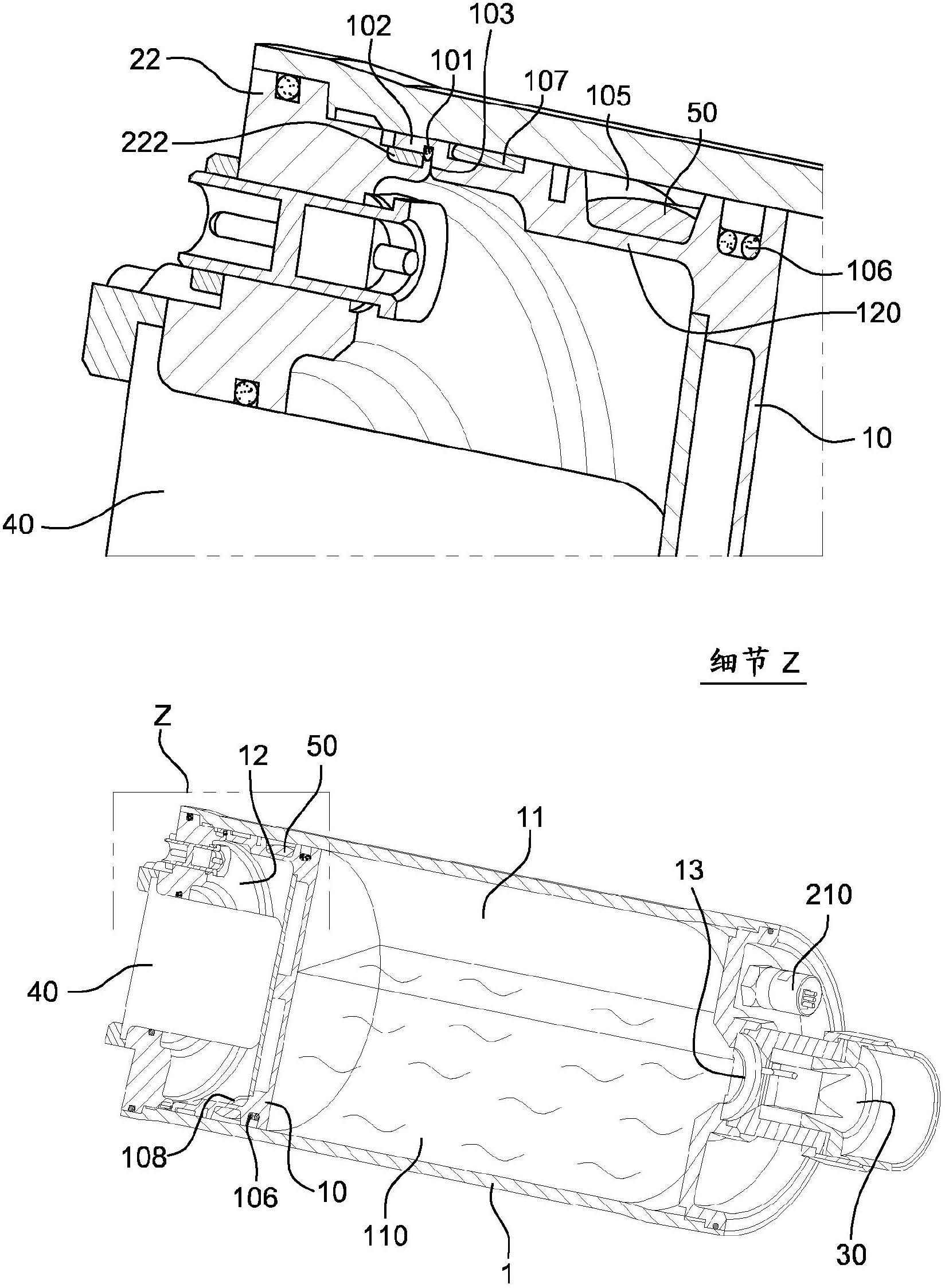
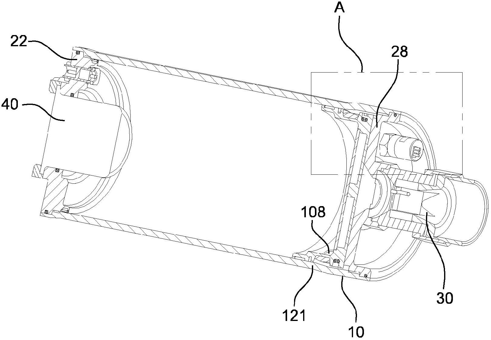
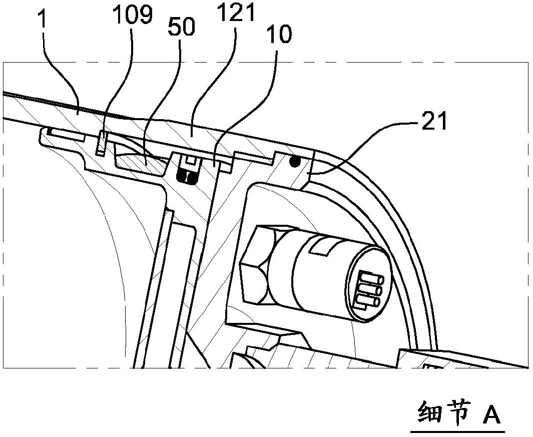
[0031] figure 1 : According to an embodiment, the fluid ejection device which is the subject of the invention comprises a cylindrical body (1) divided by a piston (10) into two chambers (11, 12) and at its end Closed by two flanges (21, 22). The first chamber ( 11 ) is partially filled with the fluid to be injected ( 110 ); the remainder of the volume is filled with an inert gas so that the pressure inside this chamber is always higher than atmospheric pressure. This first chamber communicates with an orifice ( 13 ) formed in the end flange ( 21 ), the orifice ( 13 ) being closed by a removable cap ( 30 ). The airtightness of the first chamber can be checked with means (210) for measuring the pressure in the first chamber. The second chamber (12) (called "plenum chamber") is also closed by a flange (22) which also supports a device (40), which in this case is a pyrotechnic gas A generator designed to increase the pressure in the chamber.

[0032] figure 1 Detail Z: The ...


PUM


Abstract

The invention relates to a fluid ejection device which is used specifically as an extinguisher, the ejected fluid then being an extinguishing agent in liquid or powdered form. Said device comprises: a cylindrically-shaped tank (1), which is sealingly separated perpendicularly to the axis thereof, into two chambers (11, 12), by means of a so-called piston (10) element capable of sliding axially inside the tank; a first chamber (11) containing a non-gaseous fluid (110), which is in communication with an ejection opening (13) closed by a cap (30) capable of opening at a pressure greater than or equal to a pre-determined pressure in said first chamber; a second so-called pressurization chamber (12) capable of being connected to means (40) for increasing the pressure in said chamber; and a means (101) linking the piston to the tank in complete connection in a first axial so-called storage position, which means are capable of breaking and releasing the piston in axial translation at a pressure greater than or equal to a pre-determined pressure in the pressurization tank (12), so as to cause the fluid (110) to be ejected.

Description

technical field [0001] The present invention is in the field of fluid ejection devices. Such a device is more particularly used as a fire extinguisher in which the injected fluid is an extinguishing agent in liquid or powder form. Background technique [0002] Such a device is described, for example, in International Patent Application WO2009056574 in the applicant's name. [0003] According to the state of the art, such devices consist of: [0004] a cylindrical tank divided into two sealed chambers by an axially movable piston; [0005] The first chamber contains the fluid to be injected; the first chamber communicates with the injection port, which is closed by the cap; [0006] The second chamber (referred to as the "pressurization chamber") is connected to means that increase the pressure in said chamber. [0007] To trigger the device and cause the liquid contained in the first chamber to be ejected, the pressurization chamber is enlarged by communicating the press...

Claims


Application Information

Patent Timeline
IPC IPC(8): A62C13/66A62C35/02
CPCA62C13/66A62C13/006A62C35/02
Inventor 克里斯蒂安·法布尔阿兰·比格诺莱
Owner AIRBUS OPERATIONS (SAS)
Why Eureka
Try Eureka