Mat sealing joint, electrical connector, and method of manufacture

A technology of pad joints and connectors, applied in the direction of the base/shell, etc., can solve problems such as high production troubles

Active Publication Date: 2015-05-06
APTIV TECH LTD
View PDF4 Cites 0 Cited by
  • Summary
  • Abstract
  • Description
  • Claims
  • Application Information

AI Technical Summary

Problems solved by technology

[0006] However, the asymmetric shape in turn creates problems for the high-volume manufacturing required for this type of product

Method used


Image

  • Mat sealing joint, electrical connector, and method of manufacture
  • Mat sealing joint, electrical connector, and method of manufacture
  • Mat sealing joint, electrical connector, and method of manufacture

Examples


Embodiment Construction

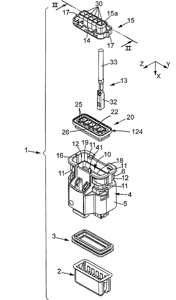
[0034] figure 1 An electrical connector 1 is shown to be connected to a mating connector (not shown). Fitted in the connector is a joint 3 of any suitable shape and material to be sandwiched between the connector 1 and the mating connector for sealing the connection.

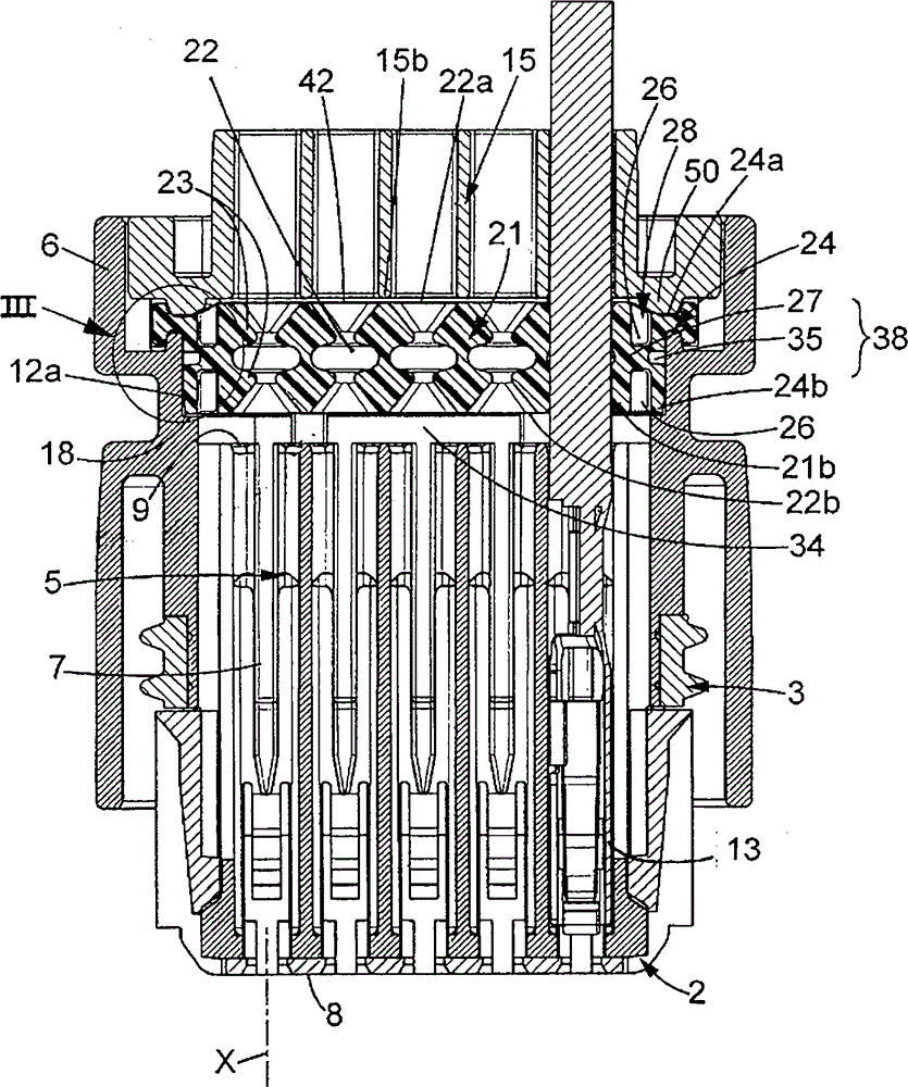
[0035] The electrical connector 1 comprises a housing comprising a housing body 4, a front grid 2 and a rear grid 15, each made of insulating thermoplastic material. The front grid 2 is locked to the front mating end of the housing body prior to assembly to the mating connector. The housing body 4 includes a front connecting portion 5 and a rear portion 6 . The connecting portion comprises a plurality of passages 7 extending along the longitudinal direction X between the front 8 and the rear 9 ( figure 2 ), where the front 8 is the face that mates with the mating connector. The passages are shaped to receive electrical terminals 13 which will be described in further detail below.

[0036] The rear part 6 p...


PUM


Abstract

A method of manufacturing a mat sealing joint made of a deformable material: providing a mold (43) having a central retention device (45) and two half cavities (46, 47) placed on both sides of said retention device, forming the joint in the cavity, withdrawing the two half-cavities (46, 47), whereby the joint is retained by cooperation of the central retention device (45) with recess of the joint.

Description

technical field [0001] The present invention relates to a gasket joint for a connector, such as an electrical, optical or optoelectronic connector, and a method of manufacturing such a gasket joint. Background technique [0002] Connectors are used in particular for connecting electrical, optical or optoelectronic devices to each other and can be used for any type of electrical, optical or optoelectronic devices. For example, such connectors may be of the type comprising an electrically insulating housing into which wires or optical fibers are inserted. In this document, electrical connectors are taken as examples, but those skilled in the art can easily transform these examples into connectors for optical applications or optoelectronic applications. [0003] Since it is undesirable for foreign substances such as dust and liquids to enter the interior of the connector, it is preferable to seal the connector against such foreign substances. Thus, the known type of connector...

Claims


Application Information

Patent Timeline
Patent Type & Authority Patents(China)
IPC IPC(8): H01R13/52
Inventor 埃尔万·古兰顿克利斯汀·坎普福特普洛·德马托斯
Owner APTIV TECH LTD
Why Eureka
Try Eureka