Novel flat plate-shearing mechanism

A shearing and flat plate technology, applied in the field of new flat plate shearing mechanism and shearing mechanism, can solve the problems of high labor intensity, low production efficiency, waste of shearing materials in the shearing mechanism, etc., so as to overcome the high labor intensity and high production efficiency. Effect

Inactive Publication Date: 2012-08-22
张世冯
View PDF0 Cites 3 Cited by
  • Summary
  • Abstract
  • Description
  • Claims
  • Application Information

AI Technical Summary

Problems solved by technology

[0003] The purpose of the present invention is to provide a new type of plate shearing mechanism, which overcomes the existing semi-manual and semi-mechanical production methods of the existing shearing mechanism, which have high labor intensity, low production efficiency, and once coordination errors occur, the shearing mechanism will be damaged The defect of cutting waste

Method used


Image

  • Novel flat plate-shearing mechanism
  • Novel flat plate-shearing mechanism

Examples


Embodiment Construction

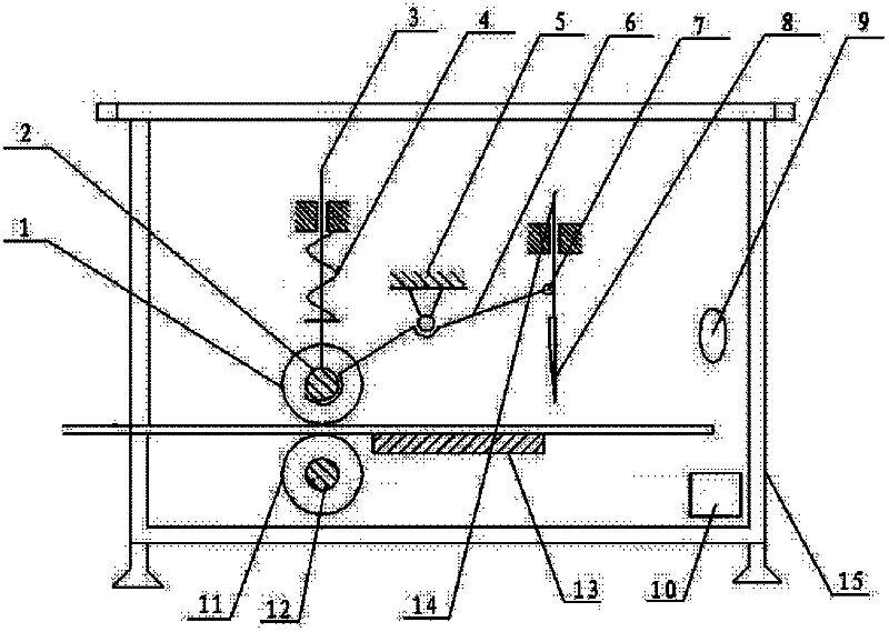
[0010] The shearing mechanism has a roller (1), and the roller (1) is installed on the deployment pressure rod (3) through the roller shaft (2), and the multi-position spring (4) is installed on the deployment pressure rod (3). The joint connecting rod (6) is installed on the supercharging support (5), and one end of the double joint connecting rod (6) is connected with the roller shaft (2), and the other end is connected to the scissors through the double joint connecting rod pin (7). The plate knife seat (14) is connected, and the single-sided cutter (8) is installed on the top of the shear plate knife seat (14), and the contact infrared ray emitting device (9) and the contact infrared ray receiving device (10) are installed on the two-way Above the guide rail (13), the bidirectional guide rail (13) is installed on the top of the shearing plate mechanism body (15), and at the lower end of the shearing plate mechanism body, positioning roller shafts (12) and positioning roller...


PUM


Abstract

The invention relates to a novel flat plate-shearing mechanism. A roller is mounted on a deployment pressure lever through a roller shaft; a multi-position spring is mounted on the deployment pressure lever; a two-section connecting rod is mounted on a supercharging support seat; one end of the two-section connecting rod is connected with the roller shaft; the other end of the two-section connecting rod is connected with a plate-shearing knife seat through a two-section connecting rod pin; a single-sided cutting knife is mounted on the plate-shearing knife seat; an contact infrared transmission device and a contact infrared reception device are mounted on a two-way guide rail; the two-way guide rail is mounted on a plate-shearing mechanism body; and a positioning roller shaft and a positioning roller are sequentially mounted at the lower end of the plate-shearing mechanism body.

Description

technical field [0001] The invention relates to a shearing mechanism, in particular to a novel plate shearing mechanism, which belongs to the technical field of shearing machinery. Background technique [0002] The shearing machine is the main machine for cutting metal materials. As far as the current shearing mechanism is concerned, it is mainly semi-manual and semi-mechanical production methods to complete the shearing. This semi-manual and semi-mechanical production mode not only exists The labor intensity is high, the production efficiency is low, and once there is a mistake in manual coordination, it will cause a waste of material cut by the shearing mechanism. Contents of the invention [0003] The purpose of the present invention is to provide a new type of plate shearing mechanism, which overcomes the labor intensity and low production efficiency of the existing semi-manual and semi-mechanical production mode of the shearing mechanism, and the shearing mechanism wi...

Claims


Application Information

Patent Timeline
Patent Type & Authority Applications(China)
IPC IPC(8): B23D15/08B23D33/02B23D33/00
Inventor 张世冯
Owner 张世冯
Why Eureka
Try Eureka