
Bicycle braking device with warning effect

A technology for bicycles and brakes, which is applied in the field of bicycle brake devices with warning effects, and can solve problems such as lack of fixing effect of the contact rod, poor contact, and position deviation of the contact rod.

Inactive Publication Date: 2012-08-22
CANKNOW INT IND
View PDF9 Cites 1 Cited by
  • Summary
  • Abstract
  • Description
  • Claims
  • Application Information

AI Technical Summary

Problems solved by technology

However, such a design will cause the rod to lack a good fixing effect, and it is easy to cause the rod to deviate in position when it is subjected to an improper external force, resulting in the rod being unable to push the contact pin of the warning element reliably, resulting in poor contact.

Method used


Image

  • Bicycle braking device with warning effect
  • Bicycle braking device with warning effect
  • Bicycle braking device with warning effect

Examples


Embodiment Construction

[0018] The following preferred embodiments are listed below in conjunction with the accompanying drawings to describe the structure and effects of the present invention in detail.

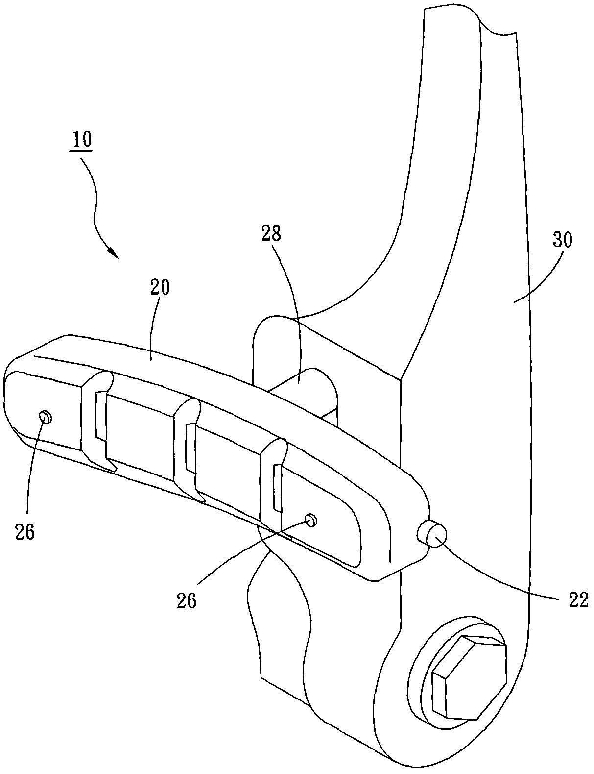
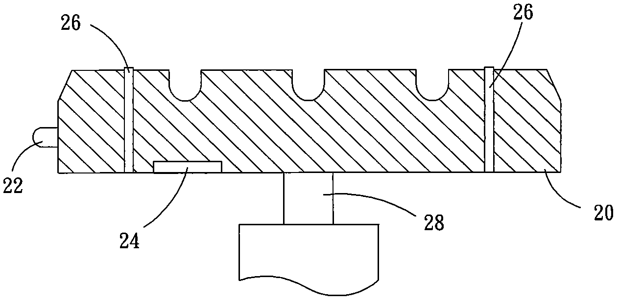
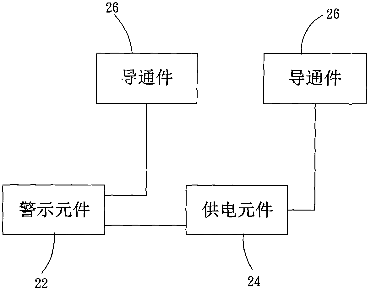
[0019] see figure 1 , the bicycle brake device 10 provided by the first preferred embodiment of the present invention is applied to the rim brake of bicycles, and mainly includes a brake block 20, a warning element 22, a power supply element 24, and two conducting elements 26 .

[0020] The brake block 20 is fixed to a brake caliper 30 via a connecting rod 28 , and can move toward the rim 32 along with the brake caliper 30 .

[0021] The warning element 22 can be a light emitting diode or a loudspeaker. Here, light emitting diode is taken as an example. In this embodiment, the warning element 22 is mounted on the rear end surface of the brake block 20 and exposed outside the brake block 20 .

[0022] The power supply element 24 is a built-in battery in this embodiment, which can be installed in ...


PUM


Abstract

The invention relates to a bicycle braking device with a warning effect. The bicycle braking device comprises a brake block, a warning element arranged at the brake block, a power supply element electrically connected to the warning element, and two conduction members arranged in the brake block, wherein the conduction members are electrically connected with the warning element and the power supply element, and one ends of the conduction members are exposed to the surface of the brake block, so that, when the brake block is controlled by a brake block calliper and forces the conduction members to touch a wheel rim or a braking plate with the exposed ends of the conduction members, an internal circuit of the brake block can be switched on, and the warning element can produce a warning signal to achieve the warning effect.

Description

technical field [0001] The invention relates to bicycle brake technology, in particular to a bicycle brake device with warning effect. Background technique [0002] China Taiwan Patent No. 553149 discloses a "brake illuminator", which mainly includes a brake block and a light-emitting unit. The brake block is fixed on a brake arm and can move with the brake arm, and has an elastic action. The light-emitting unit has a battery and a warning element. The battery is arranged in the brake block and has two electrode terminals. terminal for electrical connection. When the brake block is affected by the brake arm and touches the rim with its contact rod, the contact rod of the brake block will push the other contact pin of the warning element, so that the contact pin touches the other electrode end of the battery, At this time, the current of the battery will be turned on, and the warning element can emit light to achieve a warning effect. [0003] In the aforementioned design,...

Claims


Application Information

Patent Timeline
IPC IPC(8): B62L1/10B62J6/00
CPCB62L1/005B62L1/10B62J3/12F16D66/024
Inventor 苏伟中
Owner CANKNOW INT IND
Learn More