
Filter device

A technology of filtration equipment and filter elements, which is applied in the direction of filtration separation, membrane filter, cartridge filter, etc., and can solve problems such as difficulties

Active Publication Date: 2014-09-24
MAHLE INT GMBH
View PDF7 Cites 0 Cited by
  • Summary
  • Abstract
  • Description
  • Claims
  • Application Information

AI Technical Summary

Problems solved by technology

However, the assembly of such a filter device, in particular the installation of the annular filter element in the filter housing, has proven to be difficult

Method used


Image

  • Filter device
  • Filter device
  • Filter device

Examples


Embodiment Construction

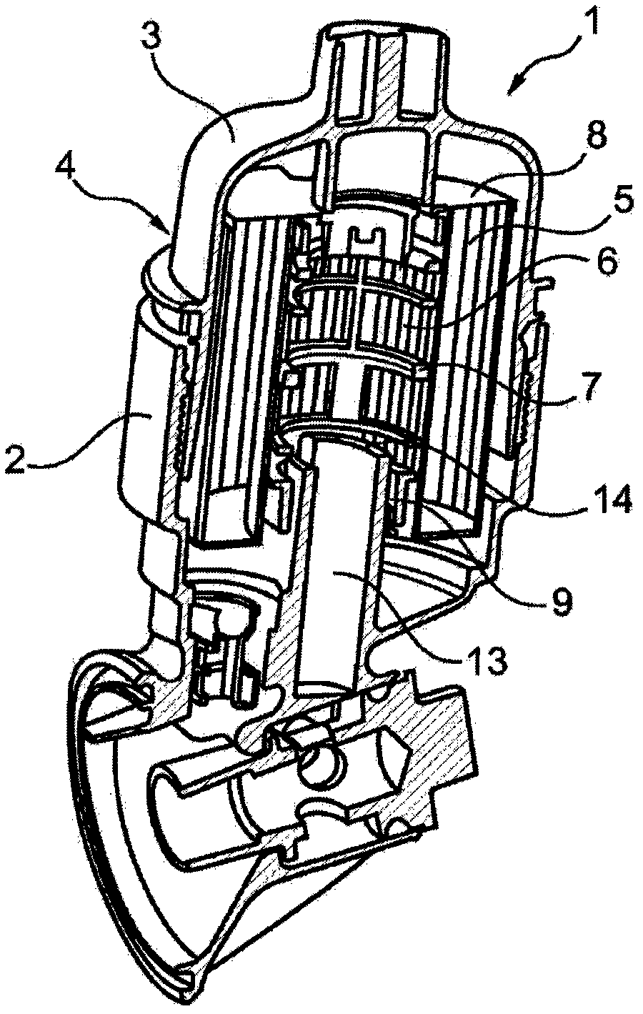
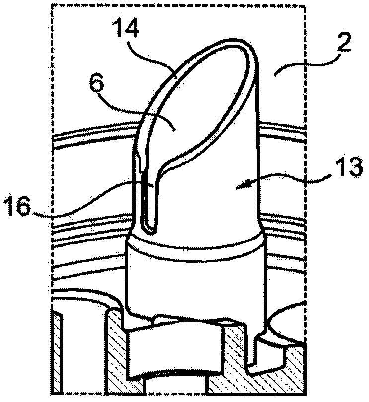
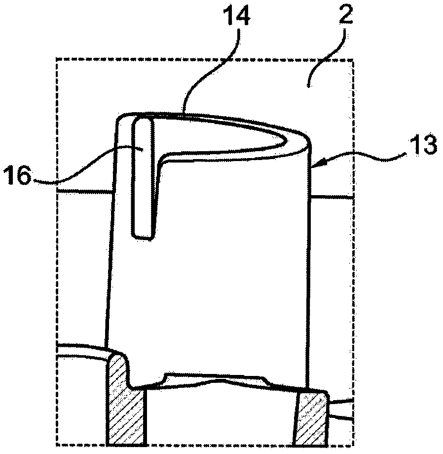
[0032] according to figure 1 , the filter device 1 according to the invention, for example an oil or fuel filter or an air filter for an engine vehicle, has a filter housing 4 formed by a filter housing crucible 2 and a filter housing cover 3, the filter housing cover 3 Can be screwed to filter housing crucible 2. Arranged within the filter housing 4 is an annular filter element 5 , which is known per se and is supported with respect to the internal cavity 6 , for example by means of an internal cover 7 of a similar support structure. The annular filter element 5 is also delimited in the axial direction in a known manner by an upper end disk 8 and a lower end disk 9 . A pin 10 protruding in axial direction from the lower end plate 9 is provided (see, e.g. Image 6 with Figure 7 ), which preferably engages in a leak-proof manner in the channel 11 on the crucible side of the filter housing and thus seals it when the filter device 1 is fully assembled. For this purpose, a se...


PUM


Abstract

The invention relates to a filter device (1), in particular an oil or fuel filter, comprising a filter housing (4) with a filter housing crucible (2) and a filter housing cover (3), an annular filter element (5 ) is arranged in the filter housing, the annular filter element (5) has an axially protruding pin (10) on the lower end plate (9), when the filter device (1) is assembled, By means of the pin, the element engages with the channel (11) on the crucible side of the filter housing. According to the invention, it is essential that a tubular dome (13) is provided on said filter housing crucible (2), said dome being in contact with said annular filter element when said filter device (1) is assembled (5) internal chamber (6) engagement, and in that a guide arc (14) is provided on the free end of said tubular dome (13), said guide arc is arranged on said annular filter element The guiding elements (15) on (5) interact. Thereby, assembly can be facilitated.

Description

technical field [0001] The invention relates to a filter device, in particular an oil or fuel filter, comprising a filter housing with a filter housing crucible and a filter housing cover. Background technique [0002] In general filter equipment, in order to ensure the use of approved annular filter equipment, pins protruding axially from the lower end plate are usually arranged on it, when the filter equipment is assembled, by means of the pin, the annular filter element engages in the in the channel on the crucible side of the filter housing and only use the filter device if the annular filter element used has the required pins in the correct position. As a result, for example, the use of non-approved annular filter elements and thus damage to the internal combustion engine can be prevented in particular. However, the assembly of such a filter device, in particular the mounting of the annular filter element in the filter housing, has proven to be difficult. Contents of...

Claims


Application Information

Patent Timeline
Patent Type & Authority Patents(China)
IPC IPC(8): B01D29/96B01D35/153
CPCB01D2201/52B01D29/96B01D2201/4046B01D35/153B01D2201/4007B01D35/16B01D27/08B01D29/15B01D35/30B01D35/306B01D2201/291B01D2201/295B01D2201/4053
Inventor 格雷戈里·德尚约翰·拉莫特
Owner MAHLE INT GMBH
Features
  • Generate Ideas
  • Intellectual Property
  • Life Sciences
  • Materials
  • Tech Scout
  • Unparalleled Data Quality
  • Higher Quality Content
  • 60% Fewer Hallucinations
Learn More