LED (Light-Emitting Diode) lamp with heat radiation structure

A technology of LED lamps and heat dissipation structures, applied in lighting and heating equipment, semiconductor devices of light-emitting elements, cooling/heating devices of lighting devices, etc., can solve the problems of dissipating heat, increasing heat dissipation area, and unable to ensure smooth airflow, etc. Achieve the effect of improving service life and improving heat dissipation performance

Active Publication Date: 2012-08-29
XIAMEN YANKON ENERGETIC LIGHTING CO LTD
View PDF8 Cites 5 Cited by
  • Summary
  • Abstract
  • Description
  • Claims
  • Application Information

AI Technical Summary

Problems solved by technology

[0003] Most of the existing LED lamps directly use their lamp cups as heat sinks, and the heat dissipation effect is not good
In order to overcome this shortcoming, some directly add heat sinks on the outer wall of the lamp cup to increase the contact area with the air, and some install a radiator in the lamp cup, but for the former, due to the The heat is mainly concentrated in the interior, and simply increasing the heat dissipation area of ​​the lamp cup cannot conduct the heat outward in a timely and effective manner. At the same time, due to the increase in the heat dissipation area, the overall weight of the lamp increases, which is not conducive to the development of small and light lamps; for the latter , the cavity surrounded by the lamp cup and the radiator can certainly form a heat conduction cavity, but because of the connection between the heat conduction cavity and the outside world, the smooth flow of air flow cannot be guaranteed, and rapid heat dissipation cannot be achieved.

Method used


Image

  • LED (Light-Emitting Diode) lamp with heat radiation structure
  • LED (Light-Emitting Diode) lamp with heat radiation structure
  • LED (Light-Emitting Diode) lamp with heat radiation structure

Examples


Embodiment 1

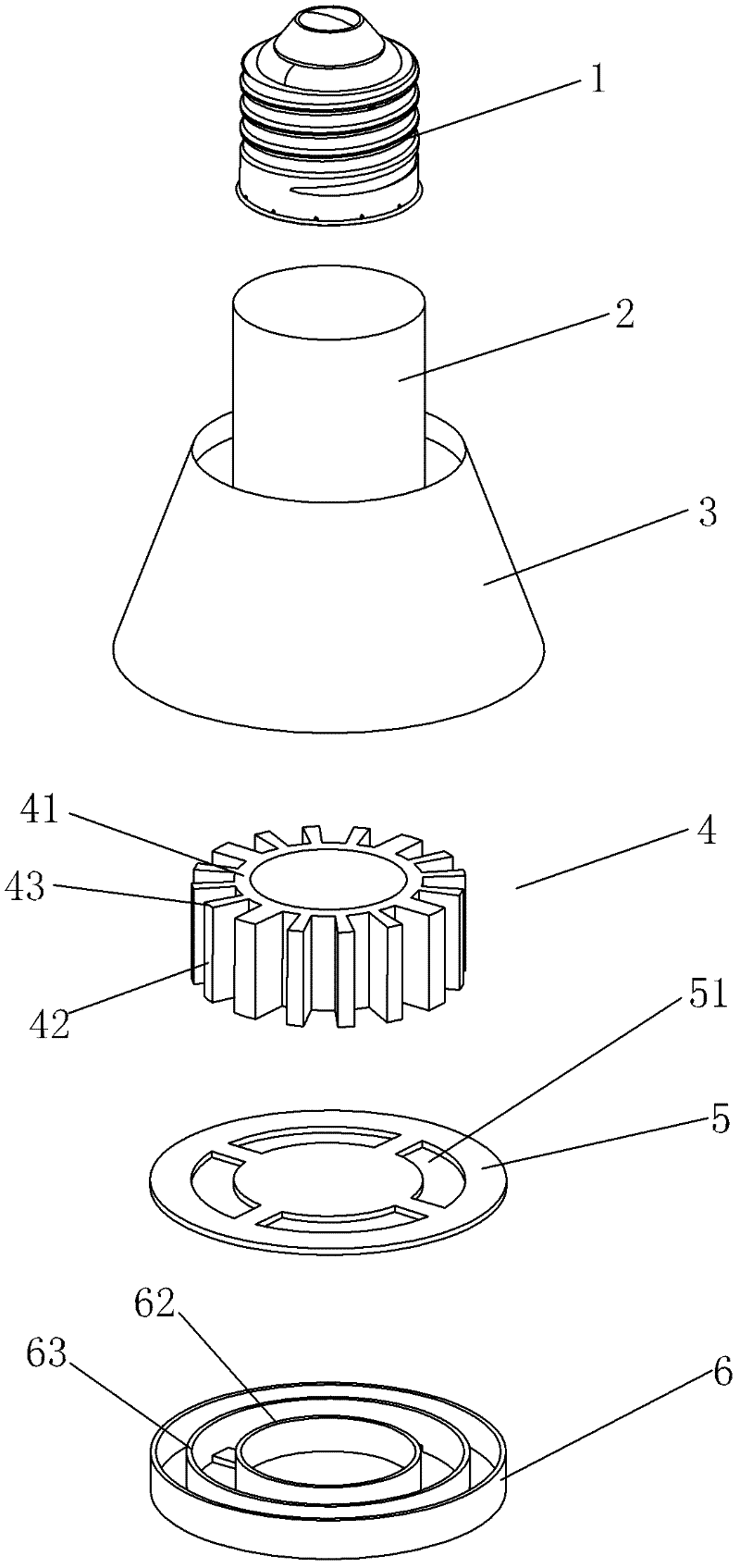
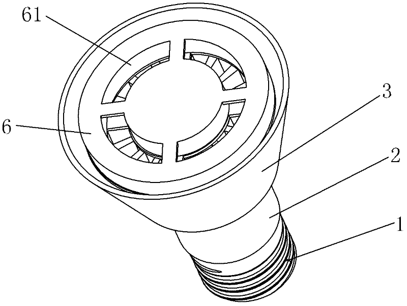
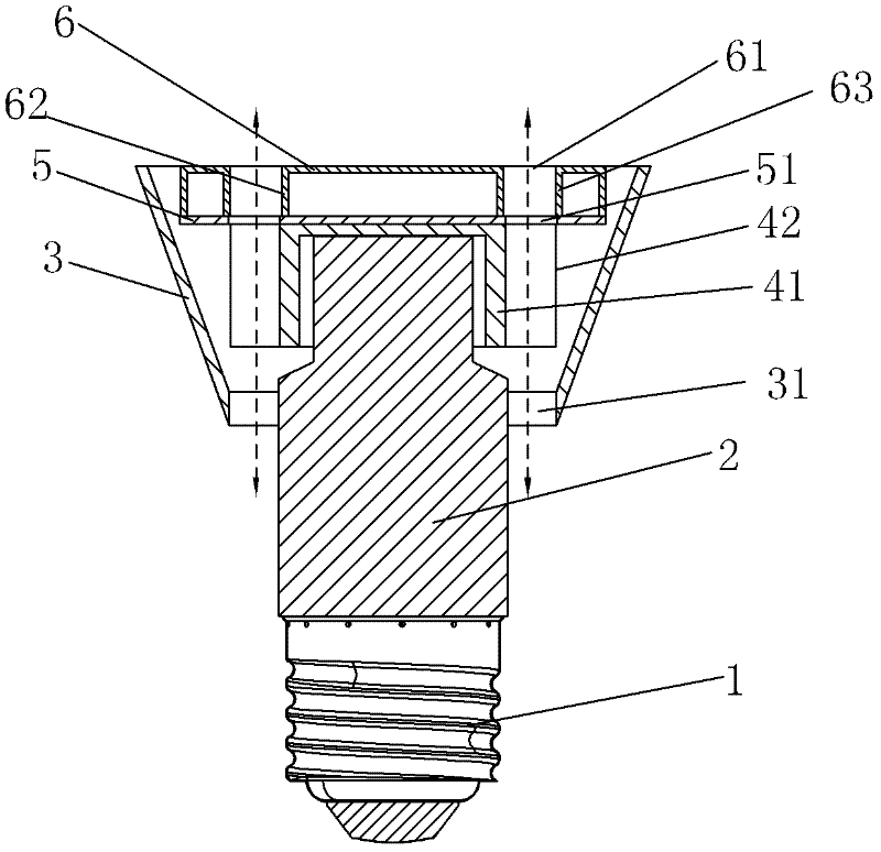
[0028] See Figure 1-Figure 3 As shown, an LED lamp with a heat dissipation structure of the present invention includes a lamp holder 1, a power board, a power board fixing cover 2, a lamp cup 3, a light source board 5 equipped with an LED light source, a lens 6 and a radiator 4. Wherein, radiator 4 is metal material, such as aluminum material or copper material etc., and it comprises hollow cylinder 41 and a plurality of cooling fins 42 that are square respectively; One end of cylinder 41 is closed, and the other end is open (here, The closed end refers to the end near the light source plate, and the open end refers to the end near the lamp cap), and a plurality of heat dissipation fins 42 are distributed on the outer wall circumference of the cylinder 41 at intervals (here, each heat dissipation fin 42 and the cylinder 41 form a connected together). The lamp cup 3 and the power board fixing cover 2 are respectively made of polymer insulating materials, wherein, both ends of...

Embodiment 2

[0036] A kind of LED lamp with heat dissipation structure of the present invention, please refer to Figure 4 , Figure 5 As shown, the difference from Embodiment 1 is that the end of the light source board 5 is located at the inner end 44 of each cooling fin of the radiator 4 along the circumference. Since the light source board 5 is circular, in other words, the light source board The radius of 5 is equal to the distance between the center of the radiator 4 and the inner end 44 of its cooling fins. In this way, the light source board 5 will not block one end of each heat conduction cavity formed by the radiator 4 and the lamp cup 3, that is, one end of each heat conduction cavity formed by the radiator 4 and the lamp cup 3 only needs to pass through the corresponding first process. The air holes 61 can form vertical communication with the outside world.

[0037] In the second embodiment, the lens 6 is also provided with the same first annular side wall 62 and second annula...

Embodiment 3

[0039] A kind of LED lamp with heat dissipation structure of the present invention, please refer to Figure 6-Figure 9 As shown, it differs from Embodiment 1 in that each heat dissipation fin 42 of the heat sink 4 is petal-shaped respectively, and a circular sheet 45 is used as a carrier: the plurality of heat dissipation fins 42 are arranged along the circular sheet. The circumference of 45 is distributed on the end surface of one side at intervals, that is, one end of each cooling fin 42 is integrally connected or fixedly connected to one side end surface of the circular sheet 45; the light source board 5 is assembled on the circular sheet 45. On the other end surface of the sheet 45, and between the light source board 5 and the circular sheet 45 is filled with thermal paste, so that the two form close contact; the circumference of the circular sheet 45 is also provided with a number of third air holes at intervals 44, and each third air hole 44 corresponds to each of the he...


PUM


Abstract

The invention discloses an LED (Light-Emitting Diode) lamp with a heat radiation structure. The LED lamp comprises a lamp head, a power panel, a fixing cover for the power panel, a lamp cup, a light source board, a heat radiator, and a lamp cover or a lens. A plurality of heat radiation fins are distributed around the heat radiator at intervals; openings are arranged at the two ends of the lamp cup; the heat radiator is mounted in the lamp cup; a heat conduction cavity is formed between each two adjacent heat radiation fins and the inner wall of the lamp cup; the light source board is provided with the heat radiator at one opening of the lamp cup; a first air vent is arranged in the lamp cover or the lens; an external diameter of the fixing cover for the power panel is less than an internal diameter of the lamp cup; a second air vent is formed by a gap between the fixing cover for the power panel and the other opening of the lamp cup; one end of each head conduction cavity is vertically communicated with the outside directly through the corresponding first air vent or the light source board and the corresponding first air vent; and the other end of each each heat conduction cavity is vertically communicated with the outside through the second air vent. With the adoption of the structure, a chimney effect is generated, so that the heat radiation properties of the LED lamp are greatly improved.

Description

technical field [0001] The invention relates to the field of LED lighting lamps, in particular to an LED lamp with a heat dissipation structure whose heat dissipation effect is significantly improved. Background technique [0002] LED lamps, also known as light-emitting diode lamps, are becoming the main product in the new generation of lighting market due to their high efficiency, energy saving, longevity, compactness and other technical characteristics, and they are powerfully driving the rapid development of the environmental protection and energy saving industry. At present, with the shrinking size of LEDs and the increasing power of LEDs, LEDs generate more and more heat, and the thermal management of LED lamps has become a key factor affecting their light quality and service life. For example, when the LED is overheated, the color coordinates and color temperature of the lamp will drift, and the luminous flux will decrease. At the same time, the service life of the lam...

Claims


Application Information

Patent Timeline
Patent Type & Authority Applications(China)
IPC IPC(8): F21S2/00F21V29/00F21Y101/02F21K9/23F21V29/77F21V29/83F21V29/89F21Y115/10
Inventor 余鹭帆
Owner XIAMEN YANKON ENERGETIC LIGHTING CO LTD
Why Eureka
Try Eureka