Zoom lens, optical apparatus and method for manufacturing zoom lens
A zoom lens and lens technology, applied in the field of zoom lens, can solve the problems of not small enough size and not good optical performance, etc., and achieve the effect of high resolution and excellent optical performance
- Summary
- Abstract
- Description
- Claims
- Application Information
AI Technical Summary
Problems solved by technology
Method used
Image

Examples
example 1
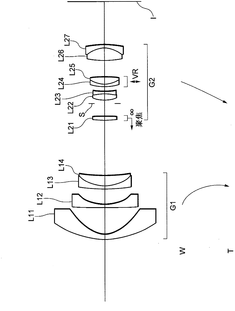
[0114] figure 1 It is a cross-sectional view of the lens configuration of the zoom lens according to Example 1 of the present application shown together with the movement trajectory of each lens group.
[0115] The zoom lens according to Example 1 is composed of a first lens group G1 having negative refractive power and a second lens group G2 having positive refractive power in order from the object side.
[0116] The first lens group G1 is composed of the following in order from the object side: a negative meniscus lens L11 having a convex surface facing the object side, a negative meniscus lens L12 having a convex surface facing the object side, and A cemented lens constructed by cementing a negative meniscus lens L13 with a convex surface facing the object side and a positive meniscus lens L14 with a convex surface facing the object side.
[0117] The second lens group G2 is composed of the following in order from the object side: a positive meniscus lens L21 having a convex surfa...
example 2
[0139] Figure 4 It is a cross-sectional view of the lens configuration of the zoom lens according to Example 2 of the present application shown together with the movement trajectory of each lens group.
[0140] The zoom lens according to Example 2 is composed of a first lens group G1 having negative refractive power and a second lens group G2 having positive refractive power in order from the object side.
[0141] The first lens group G1 is composed of the following in order from the object side: a negative meniscus lens L11 having a convex surface facing the object side, a negative meniscus lens L12 having a convex surface facing the object side, and A cemented lens constructed by cementing a negative meniscus lens L13 with a convex surface facing the object side and a positive meniscus lens L14 with a convex surface facing the object side.
[0142] The second lens group G2 is composed of, in order from the object side, a positive meniscus lens L21 having a convex surface facing th...
example 3
[0155] Figure 7 It is a cross-sectional view of the lens configuration of the zoom lens according to Example 3 of the present application shown together with the movement trajectory of each lens group.
[0156] The zoom lens according to Example 3 is composed of a first lens group G1 having negative refractive power and a second lens group G2 having positive refractive power in order from the object side.
[0157] The first lens group G1 is composed of the following in order from the object side: a negative meniscus lens L11 having a convex surface facing the object side, a negative meniscus lens L12 having a convex surface facing the object side, and a negative meniscus lens L12 having a convex surface facing the object side. A negative meniscus lens L13 with a convex surface on the side, and a positive meniscus lens L14 with a convex surface facing the object side.
[0158] The second lens group G2 is composed of the following in order from the object side: a positive meniscus len...
PUM
 Abstract
Description
Claims
Application Information
 - R&D
- Intellectual Property
- Life Sciences
- Materials
- Tech Scout
- Unparalleled Data Quality
- Higher Quality Content
- 60% Fewer Hallucinations
Browse by: Latest US Patents, China's latest patents, Technical Efficacy Thesaurus, Application Domain, Technology Topic, Popular Technical Reports.
© 2025 PatSnap. All rights reserved.Legal|Privacy policy|Modern Slavery Act Transparency Statement|Sitemap|About US| Contact US: help@patsnap.com