
Standing wave pipe coupling cavity used for wide-band low-distortion equal-amplitude equal-phase calibration

A standing wave tube and coupling cavity technology, applied in the field of acoustic measurement, can solve the problems of limited low frequency range, achieve wide frequency range, reduce waveform distortion, and low distortion

Active Publication Date: 2012-08-29
BEIJING AEROSPACE INST FOR METROLOGY & MEASUREMENT TECH +1
View PDF4 Cites 13 Cited by
  • Summary
  • Abstract
  • Description
  • Claims
  • Application Information

AI Technical Summary

Problems solved by technology

[0004] The purpose of the present invention is to provide a standing wave tube coupling cavity for wide-band low-distortion, equal-amplitude, and equal-phase calibration, which solves the problem of limited low-frequency range of microphone sensitivity relative to phase calibration sound pressure level, and realizes high dynamic range and wide frequency range. , low-distortion microphone sensitivity amplitude and phase calibration

Method used


Image

  • Standing wave pipe coupling cavity used for wide-band low-distortion equal-amplitude equal-phase calibration
  • Standing wave pipe coupling cavity used for wide-band low-distortion equal-amplitude equal-phase calibration
  • Standing wave pipe coupling cavity used for wide-band low-distortion equal-amplitude equal-phase calibration

Examples


Embodiment 1

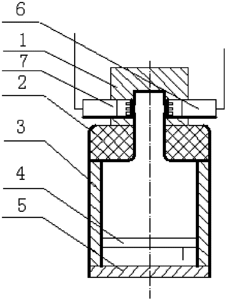
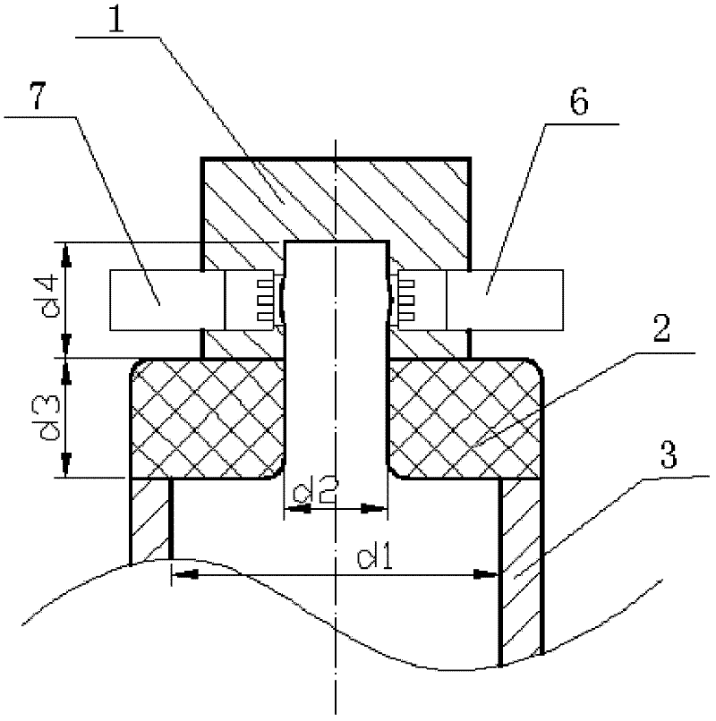
[0017] Such as figure 1 , figure 2 As shown, a standing wave tube coupling cavity for broadband low distortion, equal amplitude and equal phase calibration includes a coupling cavity 1, a variable cross-section reflector 2, a standing wave tube 3 and a rear end cover 5, wherein the hollow tube with an inner diameter d1=90mm A loudspeaker 4 is installed at the lower end of the standing wave tube 3 of the circular tube structure, and is sealed and fixed by the rear end cover 5; the variable cross-section reflective end 2 of the cylindrical cover-shaped structure with a circular through hole in the center is sealed and fixed with the upper end of the standing wave tube 3 Connection, wherein, the thickness of the variable cross-section reflective end 2 is d3=30mm, the diameter of the central circular hole of the variable cross-section reflective end 2 is d2=20mm; the coupling cavity 1 is a cylindrical structure with a cylindrical groove in the center of one end, and the central c...

Embodiment 2

[0019] Such as figure 1 , figure 2 As shown, a standing wave tube coupling cavity for broadband low distortion, equal amplitude and equal phase calibration includes a coupling cavity 1, a variable cross-section reflection end 2, a standing wave tube 3 and a rear end cover 5, wherein the hollow tube with an inner diameter d1=100mm A loudspeaker 4 is installed at the lower end of the standing wave tube 3 of the circular tube structure, and is sealed and fixed by the rear end cover 5; the variable cross-section reflective end 2 of the cylindrical cover-shaped structure with a circular through hole in the center is sealed and fixed with the upper end of the standing wave tube 3 Connection, wherein, the thickness of the variable cross-section reflective end 2 is d3=35mm, the diameter of the central circular hole of the variable cross-section reflective end 2 is d2=25mm; the coupling cavity 1 is a cylindrical structure with a cylindrical groove in the center of one end, and the cen...

Embodiment 3

[0021] Such as figure 1 , figure 2 As shown, a standing wave tube coupling cavity for broadband low distortion, equal amplitude and equal phase calibration includes a coupling cavity 1, a variable cross-section reflection end 2, a standing wave tube 3 and a rear end cover 5, wherein the hollow tube with an inner diameter of d1 = 120mm A loudspeaker 4 is installed at the lower end of the standing wave tube 3 of the circular tube structure, and is sealed and fixed by the rear end cover 5; the variable cross-section reflective end 2 of the cylindrical cover-shaped structure with a circular through hole in the center is sealed and fixed with the upper end of the standing wave tube 3 Connection, wherein, the thickness of the variable cross-section reflective end 2 is d3=40mm, and the diameter of the central circular hole of the variable cross-section reflective end 2 is d2=30mm; the coupling cavity 1 is a cylindrical structure with a cylindrical groove in the center of one end, an...


PUM


Abstract

The invention relates to the technical field of acoustic metering and particularly discloses a standing wave pipe coupling cavity used for wide-band low-distortion equal-amplitude equal-phase calibration. The lower end of the standing wave pipe in the standing wave pipe coupling cavity is provided with a loudspeaker, and the loudspeaker is also sealed and fixed by a back end cover; a variable-section reflecting end of which the center is provided with a through hole is sealed and fixed with the upper end of the standing wave pipe, and the coupling cavity with a cylinder structure is sealed and fixed in the center of the upper end of the variable-section reflecting end; moreover, the center of one end of the coupling cavity is provided with a cylindrical groove of which the diameter is the same with the diameter of the circular through hole in the center of the variable-section reflecting end; and a standard microphone and a calibrated microphone are symmetrically installed in the coupling cavity. The design of a variable section is adopted for the coupling cavity, which can provide the effects of stabilizing sound waves with large amplitude and lowering the degree of waveform distortion in the coupling cavity; and meanwhile, the calibration of the sensitivity amplitude and phase of a microphone with high dynamic range, wide frequency range and low distortion degree can be realized by the standing wave pipe coupling cavity, the dynamic range is 94 to 160dB, the frequency range is 500 to 800Hz, the degree of the waveform distortion is smaller than 1 percent, the amplitude consistency bias is smaller than 0.3 percent, and the phase bias is smaller than 0.1 degree.

Description

technical field [0001] The invention belongs to the technical field of acoustic measurement, and in particular relates to a standing wave tube coupling cavity for broadband low distortion, equal amplitude and equal phase calibration. Background technique [0002] According to the "JJG175-1998 Testing Condenser Microphone" verification regulations, the verification method of the microphone uses a piston generator as the sound source, and forms a uniform pressure field in the coupling cavity for calibration. [0003] The main structural forms of the piston generator and the coupling cavity are: a structure in which a DC motor is used to drive the eccentric wheel or a crank to drive the piston. The periodic motion of the piston generates a dynamic pressure field of a single frequency in the coupling cavity. The spatial size of the coupling cavity is required to be smaller than the wavelength 1 / 20 of. The piston generator with this structure has a single frequency, mainly 250Hz...

Claims


Application Information

Patent Timeline
Patent Type & Authority Applications(China)
IPC IPC(8): H04R29/00
Inventor 闫磊杨晓伟朱刚刘鑫孙凤举
Owner BEIJING AEROSPACE INST FOR METROLOGY & MEASUREMENT TECH
Learn More