
Image Sensor

An image sensor and generator technology, applied in the field of image sensors, can solve problems such as difficult calculation of center of gravity, pixel saturation, fast charge accumulation, etc., and achieve the effect of uniform distribution of background light brightness

Inactive Publication Date: 2016-06-15
PIXART IMAGING INC
View PDF5 Cites 0 Cited by
  • Summary
  • Abstract
  • Description
  • Claims
  • Application Information

AI Technical Summary

Problems solved by technology

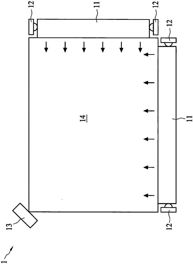
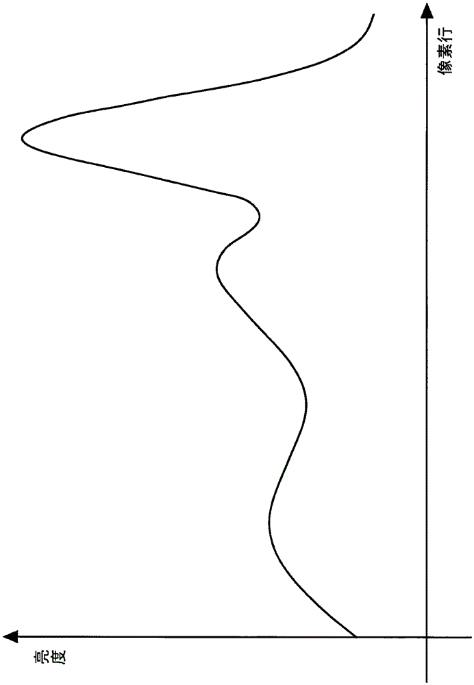
refer to figure 1 and figure 2 As shown, in the optical touch system 1, the brightness distribution of the background light projected on the image sensor 13 is not easy to be uniform.
Inhomogeneous brightness distribution will cause the following disadvantages: pixels subject to strong light will accumulate charges quickly, which will easily cause pixel saturation, which will affect the recognition of objects; in areas with weaker brightness, due to the signal-to-noise ratio noiseratio; SNR) is low, so it is easy to generate a large error in the calculation of the center of gravity of the object image; and if the object image falls on figure 2 Where the slope of the curve is large, the calculation of the center of gravity is not easy
Although this method can make the calculation of the center of gravity of the object image no longer affected by the uneven brightness distribution, it still cannot improve the problem of the center of gravity calculation error of the image generated by the object in the area with weak brightness

Method used


Image

  • Image Sensor
  • Image Sensor
  • Image Sensor

Examples


Embodiment Construction

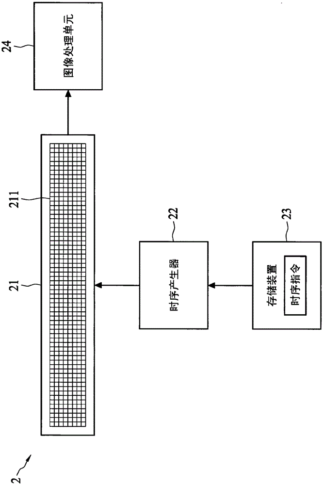
[0053] image 3 A functional block diagram of the image sensor 2 according to an embodiment of the invention is shown. Figure 4 A schematic diagram of a part of the sensing unit 211 and its control circuit in the image sensor 2 according to an embodiment of the present invention is shown. Reference image 3 As shown, the image sensor 2 includes a sensor matrix 21, a timing generator 22, a storage device 23, a plurality of electronic shutters 212, and an image processing unit 24. The sensing matrix 21 includes a plurality of sensing units 211, and the plurality of sensing units 211 are arranged in a matrix in the horizontal and vertical directions. The plurality of electronic shutters 212 are arranged corresponding to the plurality of sensing units 211. Such as Figure 4 As shown, each sensing unit 211 includes a photodetector 213, and the electronic shutter 212 is coupled to the corresponding photodetector 213 to control the exposure time of the photodetector 213. In this emb...


PUM


Abstract

The invention discloses an image sensor, which includes a sensing matrix and multiple shutter control lines. The sensing matrix has a plurality of sensing units, and each sensing unit has an electronic shutter and a light detection element, wherein the electronic shutter controls the exposure time of the light detection element. Each shutter control line is coupled to the electronic shutters in the same column or row in the sensing matrix, thereby independently controlling the exposure time of photodetection elements in different columns or rows, and making the shutters coupled to the same line Said light detecting elements of the control line have the same exposure time.

Description

Technical field [0001] The invention relates to an image sensor, in particular to an image sensor with a light source variation compensation function. Background technique [0002] The image sensor can convert light into electrical charges and process the electrical charges to output digital electrical signals that make up the image. The digital electrical signal can be stored on a storage medium or output to an image display device to present the image formed by it on the display screen, so it is very convenient to use. Because of its convenience, image sensors have been used in many electronic devices, such as digital cameras, digital cameras, mobile phones, or mice. [0003] Generally, an image sensor includes a semiconductor device, which can be a charge-coupled device (CCD) or a complementary metal oxide semiconductor (CMOS). The image sensor is usually composed of pixels arranged in a matrix. When illuminated by light, the pixels generate charges or voltages that represent...

Claims


Application Information

Patent Timeline
Patent Type & Authority Patents(China)
IPC IPC(8): H04N5/351H04N5/359
Inventor 古人豪林志新姚文翰赖鸿庆杨恕先黄昱豪吕志宏许恩峯廖祈杰
Owner PIXART IMAGING INC
Learn More