

Redundant control device
A control device and dual system technology, applied in general control systems, control/regulation systems, electrical testing/monitoring, etc., to achieve the effects of shortening the cycle, improving the safety level, and expanding the scope
- Summary
- Abstract
- Description
- Claims
- Application Information
AI Technical Summary
Problems solved by technology
Method used
Image

Examples
Embodiment approach 1
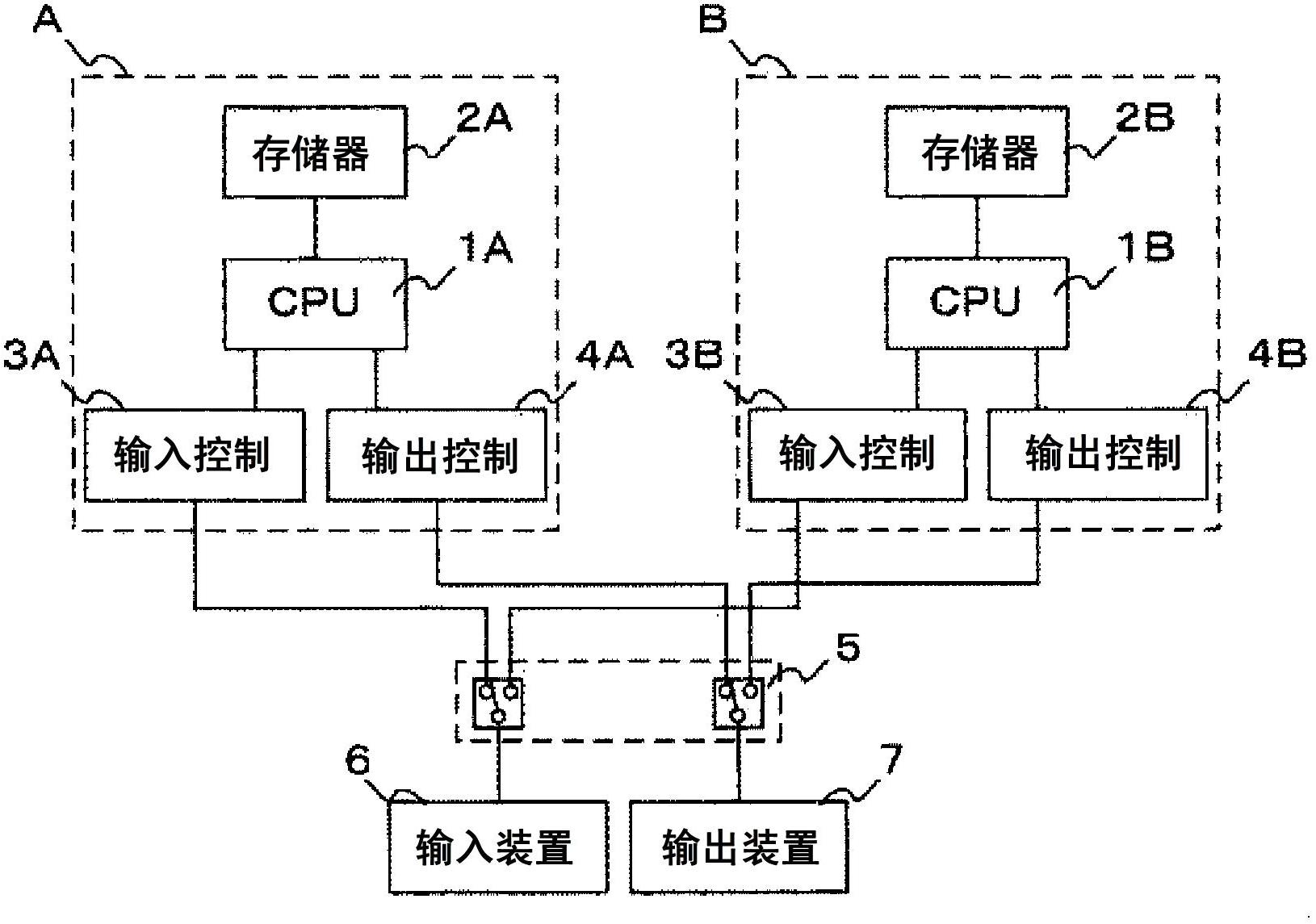
[0024] Next, Embodiment 1 of the dual system control device according to the present invention will be described with reference to the drawings. figure 1 It is a schematic configuration diagram of the dual system control device in Embodiment 1 of the dual system control device according to the present invention. figure 1 In , the dual system control device is duplexed by the A system as the control system and the B system as the other control system. These control systems A and B respectively include CPUs 1A, 1B that perform arithmetic processing, etc., memories 2A, 2B connected to these CPUs, and input control units 3A, 3B connected to each CPU and that transmit input information from controlled objects to these CPUs. , and the output control units 4A, 4B that control the output information of the output control device 7 . By connecting these input control units 3A and 3B and output control units 4A and 4B to a switching device 5 that performs system switching based on a s...
Embodiment approach 2
[0028] Hereinafter, Embodiment 2 of a dual-system control device according to the present invention will be described focusing on portions different from Embodiment 1 with reference to the drawings. Figure 4 It is a schematic configuration diagram of a dual system control device in Embodiment 2. In addition to the configuration of Embodiment 1, a data communication line 8 connected between CPUs 1A and 1B is included. The diagnosis status of the self-diagnosis system is referred to between the two systems A and B via the data communication line. The self-diagnosis system sets a flag for this diagnosis state, and when the diagnosis is completed, it is regarded as "diagnosis completed", and when the diagnosis is in progress, it is regarded as "diagnosis in progress".
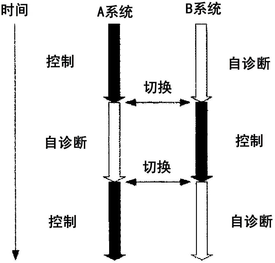
[0029] Next, the operation of the dual-system control device will be described focusing on the differences from the first embodiment. Figure 5 It is a conceptual diagram showing the outline of operations in Emb...
Embodiment approach 3
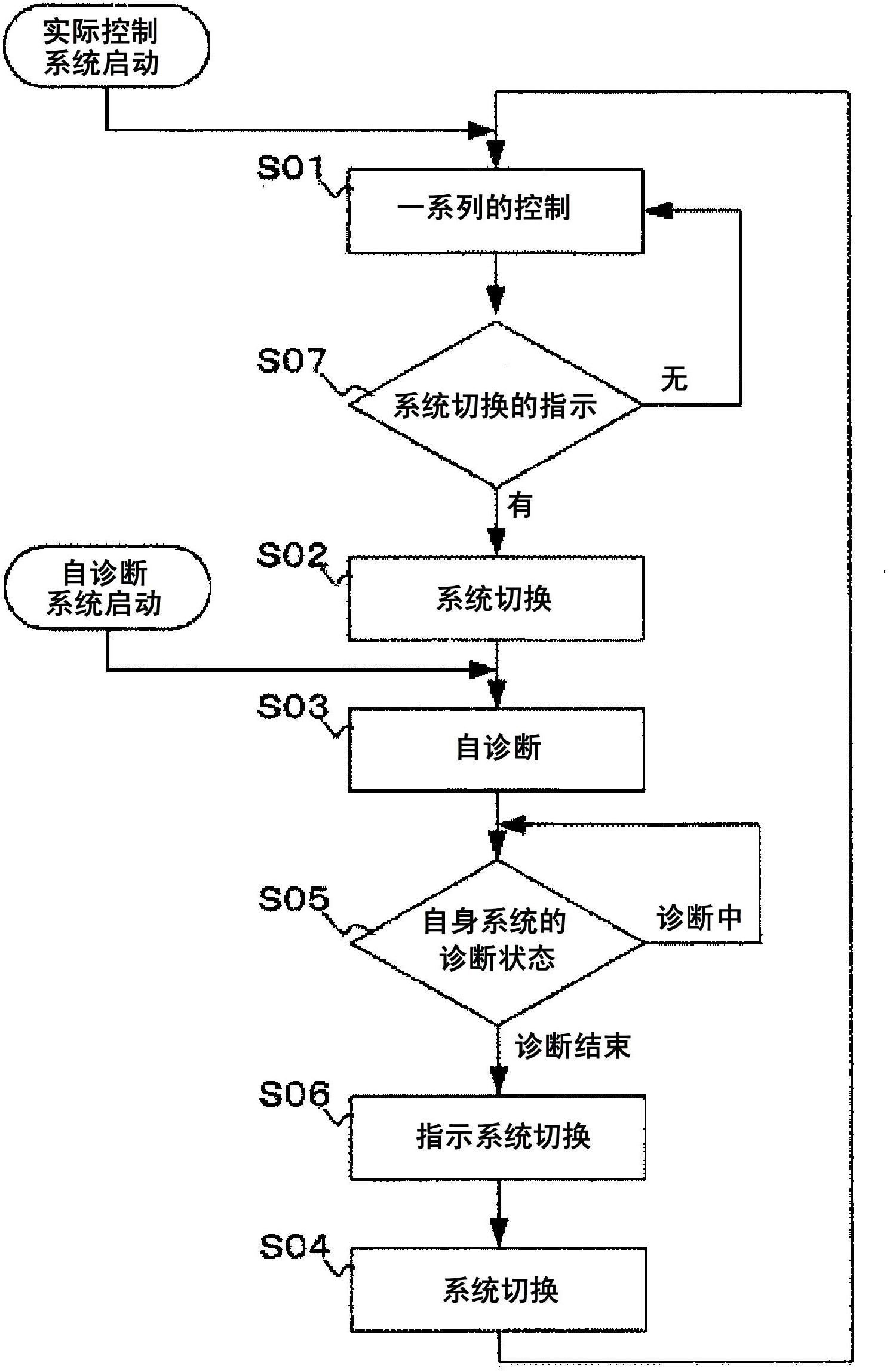
[0032] Hereinafter, Embodiment 3 of a dual-system control device according to the present invention will be described focusing on portions different from Embodiment 2 with reference to the drawings. Figure 7 It is a flowchart in Embodiment 3 of the dual system control apparatus concerning this invention. and Image 6The difference is that when the self-diagnosis system detects an abnormality through self-diagnosis, it notifies the actual control system that an abnormality has occurred. That is, when system B performing self-diagnosis as a self-diagnosis system detects an abnormality in its own system through self-diagnosis (S302), it notifies system A of the actual control system via the data communication line 8 of the abnormality (S303). System A completes a series of control processes, and refers to the operating state of system B, but in the case of an abnormality, does not issue a system switching instruction, and continues control processes sequentially (S01). If the ...
PUM
 Abstract
Description
Claims
Application Information