Control device for scanning electromagnet and particle beam therapy apapratus
a control device and electromagnet technology, applied in radiation therapy, x-ray/gamma-ray/particle-irradiation therapy, therapy, etc., can solve the problem that the controller of the control of the electromagnet is likely to cause its failur
- Summary
- Abstract
- Description
- Claims
- Application Information
AI Technical Summary
Benefits of technology
Problems solved by technology
Method used
Image
Examples
embodiment 1
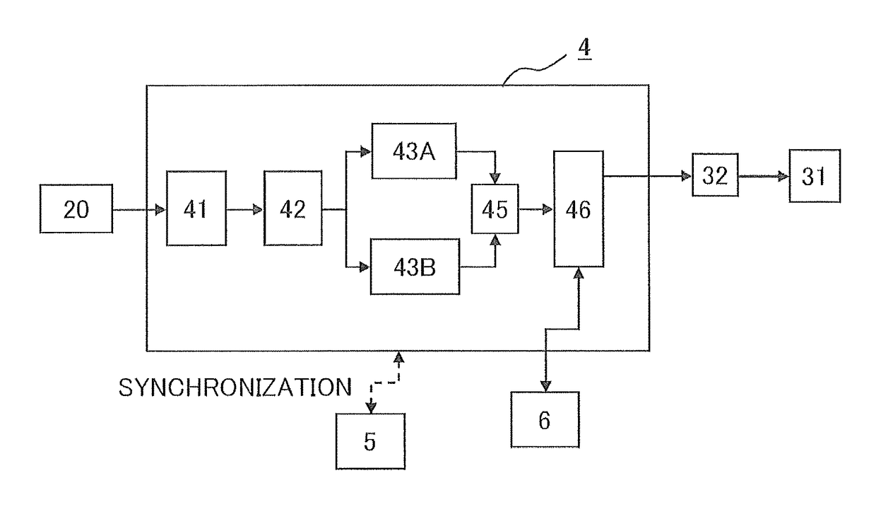
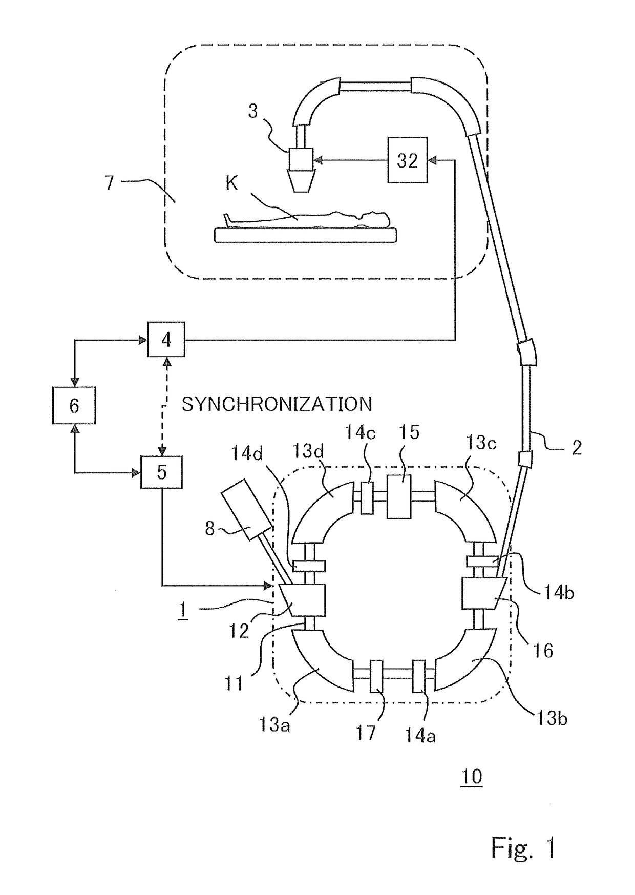
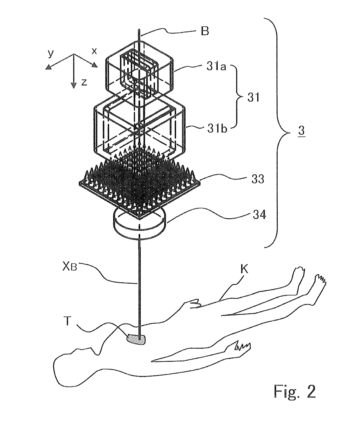
[0021]Hereinafter, a configuration of a particle beam therapy apparatus according to Embodiment 1 of the invention will be described. FIG. 1 to FIG. 3 are given for illustrating a configuration of the particle beam therapy apparatus according to Embodiment 1 of the invention, in which FIG. 1 is a diagram for illustrating an overall configuration of the particle beam therapy apparatus, FIG. 2 is a diagram showing a configuration of an irradiation device in the particle beam therapy apparatus, and FIG. 3 is a brook diagram showing a configuration of a controller (control unit) that controls a scanning electromagnet.
[0022]The particle beam therapy apparatus 1 according to Embodiment 1 of the invention is characterized in the configuration of the control device that controls a scanning electromagnet for performing scanning irradiation. Specifically, a processing line of a command value for driving the scanning electromagnet is made redundant, so that a failure is detected by comparing o...
embodiment 2
[0047]In Embodiment 1, there have been shown a situation where the conversion from the treatment plan data calculated by the external treatment plan device to the command value for the scanning electromagnet (or its driving power source) is performed by the command-value processing unit that is made redundant in the controller related to the irradiation device. This is because the conversion from the treatment plan data to the command value is dependent on the property of each electromagnet, so that it is natural to cause the controller that is given as a pair with the electromagnet to perform the conversion. However, it is not to say that the conversion can not be performed by a device other than the controller related to the irradiation device (for example, the treatment plan device). In Embodiment 2, there is shown a situation where the conversion to the command value is performed by an external device.
[0048]FIG. 4 is a block diagram for illustrating a configuration of a controll...
embodiment 3
[0054]In Embodiments 1 and 2, the error detection unit (comparator unit 45) and an error notification means (interface 46) are both included in the controller for the irradiation device (control unit 4, 204). In these cases, it is unable to take a measure against a trouble caused by noise or the like that is carried on the signal line through which the command value is transmitted from the control unit 4 to the scanning electromagnet 31 (or driving power source 32). Depending on the situation, there is a demand that the comparison in command-value processing is to be performed as much as possible at the periphery. Thus, in the particle beam therapy apparatus according to Embodiment 3, the error detection means and the error notification means are placed in the driving power source for the scanning electromagnet as a part other than the controller for the irradiation device.
[0055]FIG. 5 is a block diagram showing a configuration of a controller (control unit) for controlling an irrad...
PUM
 Abstract
Description
Claims
Application Information
 - R&D
- Intellectual Property
- Life Sciences
- Materials
- Tech Scout
- Unparalleled Data Quality
- Higher Quality Content
- 60% Fewer Hallucinations
Browse by: Latest US Patents, China's latest patents, Technical Efficacy Thesaurus, Application Domain, Technology Topic, Popular Technical Reports.
© 2025 PatSnap. All rights reserved.Legal|Privacy policy|Modern Slavery Act Transparency Statement|Sitemap|About US| Contact US: help@patsnap.com


