Medical particle irradiation apparatus

a technology of irradiation apparatus and medical particles, which is applied in the field of medical particle irradiation apparatus, can solve the problems of complex configuration and insufficient simplification of configuration, and achieve the effect of simplifying the structur

Inactive Publication Date: 2005-06-07
HITACHI LTD +1
View PDF9 Cites 136 Cited by
  • Summary
  • Abstract
  • Description
  • Claims
  • Application Information

AI Technical Summary

Benefits of technology

[0014]It is therefore the object of the present invention to provide a medical particle irradiation apparatus which ensures more simplified structure and allows formation of the substantially level access floor regardless of the position of the irradiation unit which emits particle beams.
[0015]The above object can be achieved by providing an anti-corotation unit which is in contact with both a first frame located within and supported by a rotating gantry such that it can rotate relative to the rotating gantry and a second frame fixedly located opposite the first frame and which prevents the first frame from rotating together with the rotating gantry during rotation of the rotating gantry. Further, the flexible moving floor, interposed between the first and second frames, is engaged with the first and second frames in such a manner as to move freely such that its bottom is substantially level, that it forms therein a particle irradiation room into which a therapy bed is slid and that it moves as the rotating gantry rotates.
[0016]Since the anti-corotation unit is in contact with the first frame, located within the rotating gantry such that it can rotate relative to the rotating gantry, and the fixed second frame, the anti-corotation unit which is in contact with the second frame can prevent rotation of the first frame even if the first frame attempts to rotate together with the rotating gantry during rotation of the rotating gantry. Therefore, the positions of the first and second frames which are located opposite each other can be kept substantially unchanged even if the rotating gantry rotates. Consequently, it is possible for the flexible moving floor to form a substantially level access floor regardless of the position of the irradiation unit emitting particle beams.
[0017]Moreover, since the anti-corotation unit is located on the rotating gantry, it is moved in the rotating gantry's rotation direction as a result of rotation of the rotating gantry. However, the present invention eliminates the need for the drive motor described in Patent Document 1 which rotates the mobile ring rail in the direction opposite to the rotation direction of the radiation irradiation unit by the same amount as the amount of rotation of the radiation irradiation unit and the drive unit exclusively for the anti-corotation unit, an equivalent of the motor-operated cylinder described in Patent Document 2 which moves the locking rod. The present invention does not require any exclusive drive unit for the anti-corotation unit and any control unit for this drive unit, thus allowing simplification of the structure.

Problems solved by technology

However, this prior art requires a drive motor for rotating the mobile ring rail in the direction opposite to the rotating gantry's rotation direction and a tilt sensor for detecting the relative positional relationship between the semicylindrical passages formed at the fixed and mobile ring rails and moreover a control unit for controlling them, thus making the configuration complex.
Although the drive motor and the tilt sensor in the prior art described in Patent Document 1 are not needed, the prior art described in Patent Document 2 additionally requires locking rods, motor-operated cylinders and a control unit for causing the locking rod to extend or retract with rotation of the particle irradiation unit and attaching and detaching the locking rod, thus resulting in insufficient simplification of the configurations.

Method used


Image

  • Medical particle irradiation apparatus
  • Medical particle irradiation apparatus
  • Medical particle irradiation apparatus

Examples


Embodiment Construction

[0032]An embodiment of the present invention will now be described with reference to the drawings.

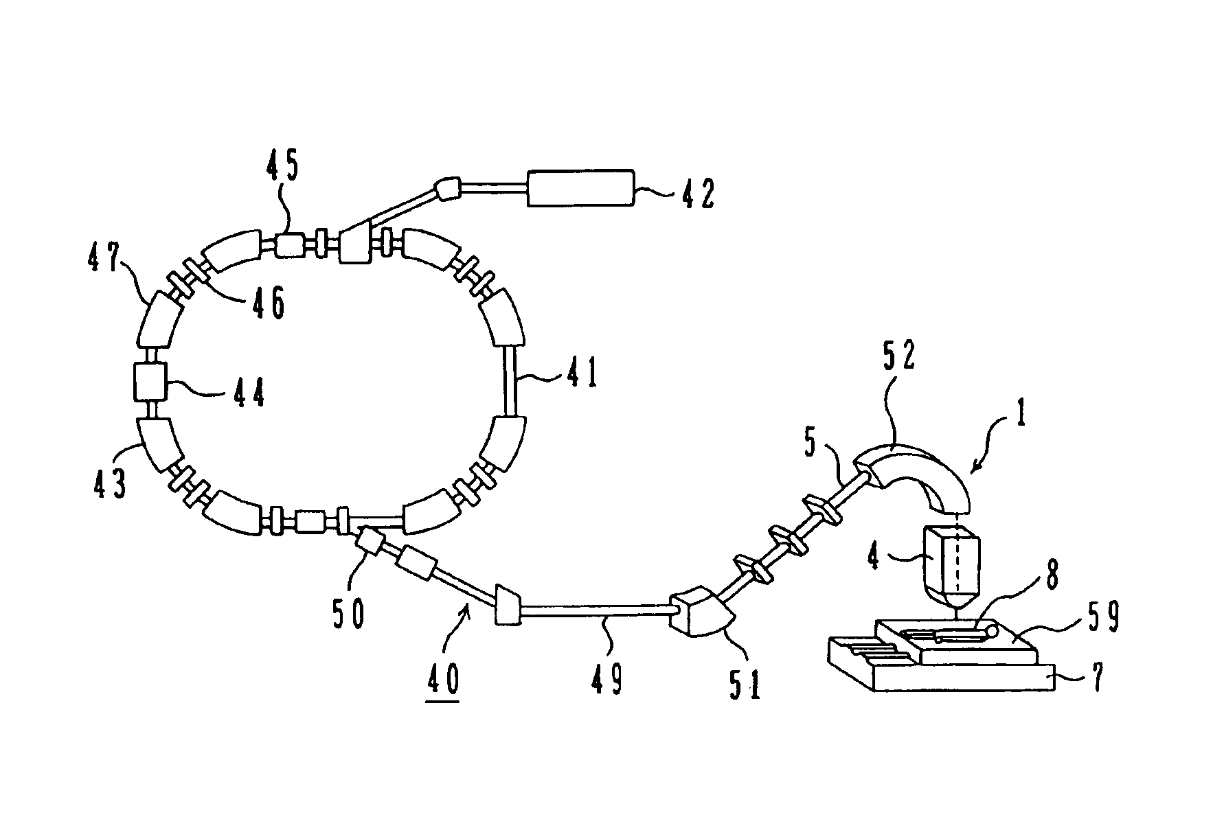
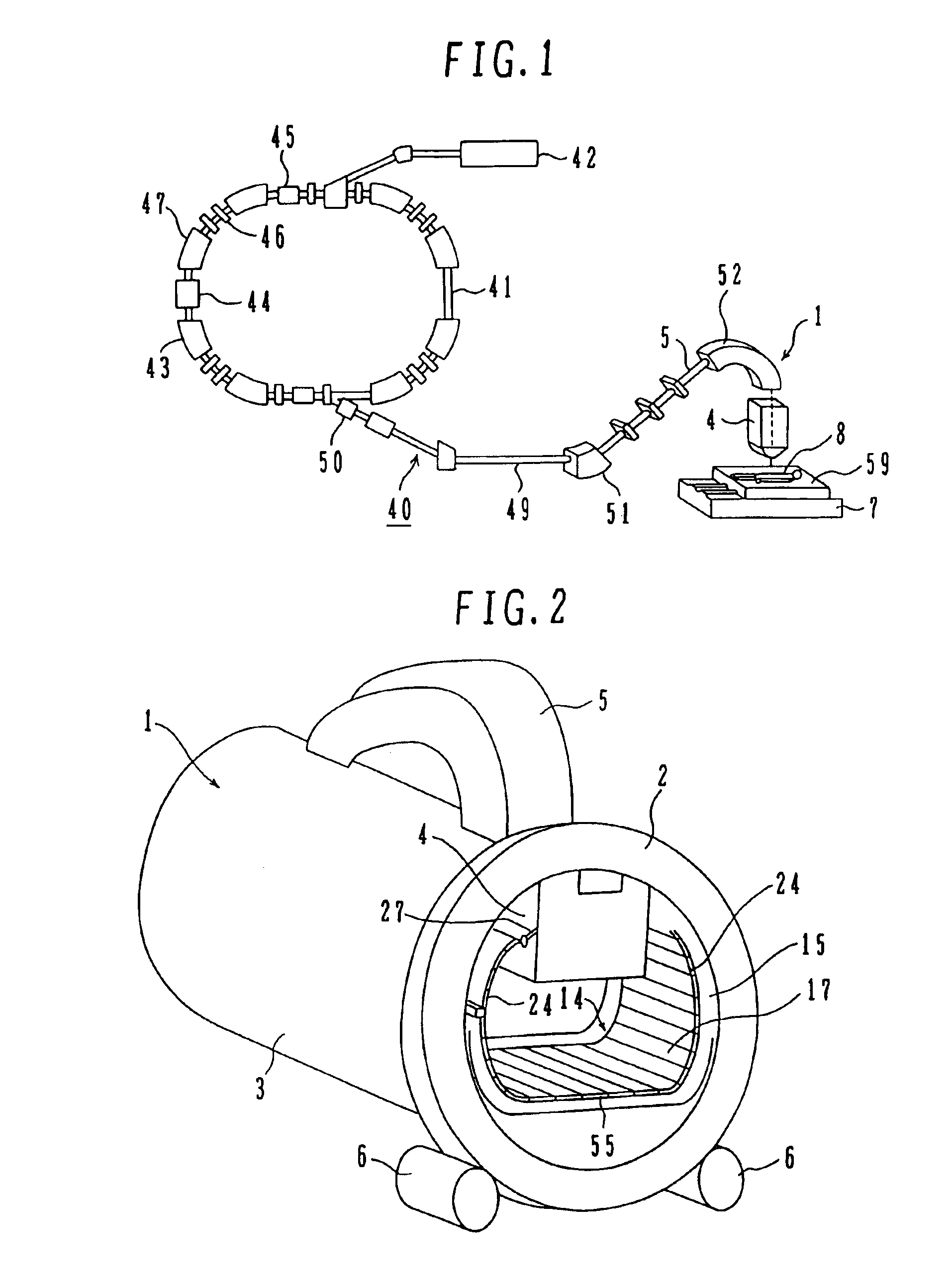
[0033]A medical particle irradiation apparatus of this embodiment is described referring to FIGS. 1 and 2. The medical particle irradiation apparatus of this embodiment is designated at 40 and comprises a charged particle beam generating unit 41 and a rotating gantry 1. The charged particle beam generating unit (particle beam generating unit) 41 has an ion source not shown, a preaccelerator 42 and a synchrotron 43. Ions generated in the ion source (e.g., proton ions (or carbon ions)) are accelerated by the preaccelerator 42 (e.g., linear accelerator). The ion beam emitted by the preaccelerator 42 enters the synchrotron 43. That beam which is a charged particle beam (particle beam) is accelerated in the synchrotron 43 as it is given energy by radio-frequency power applied by a radio frequency accelerating cavity 44. After the energy of the ion beam orbiting within the synchrotron 43 is r...


PUM


Abstract

Disclosed is a medical particle irradiation apparatus comprising a rotating gantry 1 including an irradiation unit 4 emitting particle beams; an annular frame 16 located within and supported by the rotating gantry 1 such that it can rotate relative to the rotating gantry 1; an annular frame 15 fixedly located opposite the annular frame 16; an anti-corotation mechanism 34 being in contact with both the annular frames 16 and 15 to prevent the annular frame 16 from rotating together with the rotating gantry 1 during rotation of the rotating gantry 1; and a flexible moving floor 17 interposed between the annular frames 15 and 16, the flexible moving floor 17 being engaged with the annular frames 15 and 16 in such a manner as to move freely such that its bottom is substantially level and that it moves as the rotating gantry rotates.

Description

[0001]This application is a continuation of U.S. Pat. application Ser. No.: 10 / 426,883 filed May 1, 2003, now U.S. Pat. No. 6,803,591, which is hereby incorporated by refence.BACKGROUND OF THE INVENTION[0002]1. Field of the Invention[0003]The present invention relates generally to a medical particle irradiation apparatus, and more particularly to a medical particle irradiation apparatus which is suitable for rotating around the patient and irradiating the patient with particle beams from a desired location in the circumferential direction.[0004]2. Description of the Related Art[0005]Particle beams (e.g., proton beam) have captured the spotlight in recent years in radiation therapy (treatment) for cancer as they can treat cancer with relatively small damage to normal cells.[0006]An example of rotary irradiation room for radiation therapy using particle beams is described in Patent Document 1. This rotary irradiation room for radiation therapy has a semicylindrical path with a level b...

Claims


Application Information

Patent Timeline
Patent Type & Authority Patents(United States)
IPC IPC(8): A61N5/10A61N5/01G21K5/10G21K5/04
CPCA61N5/10A61N5/1081A61N2005/1087
Inventor MURAMATSU, YUTAKAASANO, HIDEHITOSAGAWA, WATARUAKIYAMA, HIROSHIYAMASHITA, TSUTOMU
Owner HITACHI LTD
Why Eureka
Try Eureka