
Driving device for movable single-roller crusher trolley

A single-roller crusher and single-roller crushing technology, used in grain processing and other directions, can solve the problems of high labor intensity and affect labor productivity, and achieve the effect of saving labor, shortening equipment maintenance time, and convenient operation.

Active Publication Date: 2013-10-23
MCC NORTH (DALIAN) ENG TECH CO LTD
View PDF6 Cites 0 Cited by
  • Summary
  • Abstract
  • Description
  • Claims
  • Application Information

AI Technical Summary

Problems solved by technology

At present, it is generally used to manually pull forward and push backward. The disadvantage of this method is: the manual labor intensity is high, and the operation can only be performed after the ambient temperature drops, which affects labor productivity.

Method used


Image

  • Driving device for movable single-roller crusher trolley

Examples


Embodiment Construction

[0011] The specific implementation manner of the present invention will be described below in conjunction with the accompanying drawings.

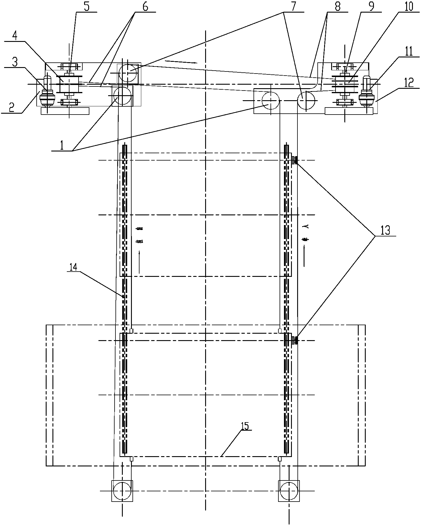
[0012] Such as figure 1 As shown, the driving device of the mobile single-roll crusher trolley of the present invention includes the trolley running track 14 respectively arranged under the single-roll crusher, and the single-roll crusher platform that walks on the trolley running track 14 The car 15 and the electric control device arranged on the single-roll crusher are characterized in that the single-roll crusher trolley 15 is respectively connected with the single-roll crusher trolley pull-in drive device and the pull-out drive device. Two sets of limit switches 13 are arranged beside the running track 14 of the trolley, and the two sets of limit switches 13 are connected with the electric control device on the single-roll crusher respectively, and the two sets of limit switches 13 are respectively installed on the single roller crushe...


PUM


Abstract

The invention belongs to the technical field of trolleys for crushing sinter, and in particular relates to a driving device for a movable single-roller crusher trolley. The device comprises a trolley running track arranged below a single-roller crusher, the single-roller crusher trolley running on the trolley running track, and an electric control device arranged on the single-roller crusher, and is characterized in that the single-roller crusher trolley is respectively connected with a single-roller crusher trolley pull-in driving device and a single-roller crusher trolley pull-out driving device; and two sets of limit switches are arranged beside the trolley running track and connected with the electric control device on the single-roller crusher. The device has a simple structure, is convenient to operate and is practical and reliable, and the maintenance time of equipment is greatly shortened.

Description

technical field [0001] The invention belongs to the technical field of trolleys for crushing sintered ore, in particular to a driving device for mobile single-roller crusher trolleys. Background technique [0002] The single-roller crusher is used to crush large pieces of sintered ore unloaded by the trolley of the sintering machine, and the crushing particle size is determined by the gap between the upper grate plates placed on the trolley under the toothed rollers. Due to the high ambient temperature (about 750-850°C), the upper grate plate of the trolley is severely worn, and the trolley needs to be pulled out frequently to replace the grate plate, and then pulled under the toothed rollers to continue production. At present, it is generally used to pull forward and push back manually. The disadvantage of this method is that the labor intensity is high, and it needs to wait until the ambient temperature drops before operating, which affects labor productivity. Contents o...

Claims


Application Information

Patent Timeline
Patent Type & Authority Patents(China)
IPC IPC(8): B02C21/02
Inventor 林宏邦张忠波
Owner MCC NORTH (DALIAN) ENG TECH CO LTD
Learn More