Boot-shaped profile line cam

A cam and shoe-shaped technology, applied in the direction of engine components, machines/engines, charging systems, etc., can solve the problems of increasing the control difficulty of the control system, excessive pollutant emissions, and loud engine operating noise

Inactive Publication Date: 2012-09-12
HARBIN ENG UNIV
View PDF6 Cites 2 Cited by
  • Summary
  • Abstract
  • Description
  • Claims
  • Application Information

AI Technical Summary

Problems solved by technology

Although the constant velocity cam has been widely used in the actual fuel injection system and has the advantage of being easy to control the injection law, it also has disadvantages: 1. The fuel injection system using the constant velocity cam concentrates on the fuel injection duration of the fuel injection system. In the forward and constant speed stage of the stroke, it is impossible to realize the shoe-shaped injection that is slow first and then rapid, which makes the engine work louder and emits more pollutants; Due to the different requirements on the fuel injection pressure and fuel injection rate, due to the high movement speed of the plunger follower in the constant velocity stage, the fuel injection pressure and fuel injection rate of the pre-injection are too large, which increases the control system's ability to control the small fuel injection volume. The difficulty of control makes it last too long, and the fuel injection volume is too large, which cannot well achieve the purpose of pre-injection to reduce noise and reduce the generation of pollutants, and thus cannot meet the requirements of emission regulations and economy

Method used


Image

  • Boot-shaped profile line cam
  • Boot-shaped profile line cam
  • Boot-shaped profile line cam

Examples


Embodiment Construction

[0046] The present invention is described in more detail below in conjunction with accompanying drawing example:

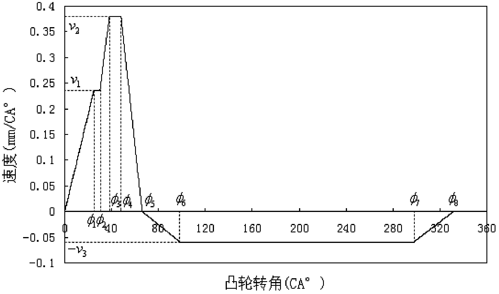
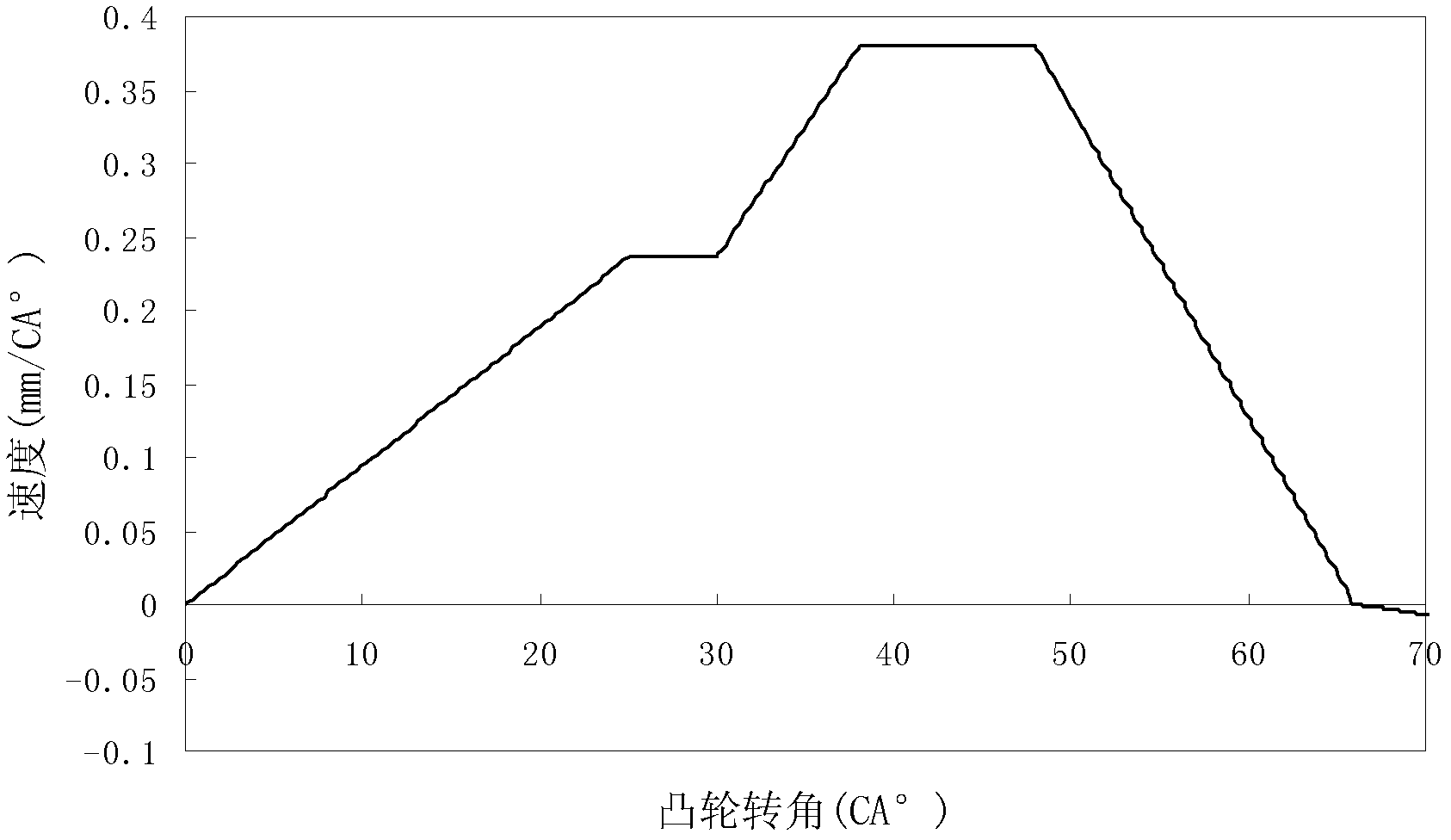
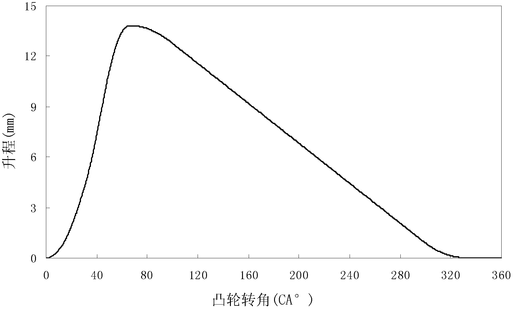
[0047] 1 to 3, the shoe cam profile of the present invention, its thrust section corresponds to the forward constant acceleration stage [0°, φ 1 ], working section [φ 1 , φ 4 ] and the forward and other deceleration stages [φ 4 , φ 5 ], the return section of the cam corresponds to the reverse constant acceleration stage of the plunger follower motion law [φ 5 , φ 6 ], reverse constant velocity stage [φ 6 , φ 7 ](velocity is v 3 ) and deceleration stages such as reverse [φ 7 , φ 8 ]. The cam working section includes two constant speed stages [φ 1 , φ 2](velocity is v 1 ) and [φ 3 , φ 4 ](velocity is v 2 ) and a constant acceleration stage [φ 2 , φ 3 ]. The equations of motion for each segment of the plunger follower are:

[0048] 1. Forward constant acceleration stage [0°, φ 1 ]

[0049] The rate parameter equation is: (φ∈[0°, φ 1 ])

[00...


PUM


Abstract

The invention aims to provide a boot-shaped profile line cam which comprises an extending stroke section and a return stroke section, wherein the extending stroke section corresponds to the forward uniform acceleration phase, the working phase and the forward uniform deceleration phase of the movement rule of a plunger follower; the return stroke section corresponds to the reversal uniform acceleration phase, the reversal uniform speed phase and the reversal uniform deceleration phase of the movement rule of the plunger follower, and the speed in the reversal uniform speed phase is v3; and the working phase also comprises two uniform speed phases and a uniform acceleration phase, and the speeds in the two uniform speed phases are respectively v1 and v2. With the boot-shaped profile line cam, different requirements of main injection and pilot injection on injection pressure and injection speed in the secondary injection of a diesel can be met at the same time, and the boot-shaped injection is realized in single injection.

Description

technical field [0001] The present invention relates to cams in the field of engines. Background technique [0002] In the traditional technology, the fuel supply pump cam used in the electronic control fuel injection system of diesel engine is a constant velocity cam, and its thrust section corresponds to the positive constant acceleration, forward constant velocity and forward constant deceleration stages of the plunger follower movement law, and the return stroke The segment corresponds to the reverse constant acceleration, reverse constant velocity and reverse deceleration stages of the motion law of the cam plunger follower. Although the constant velocity cam has been widely used in the actual fuel injection system and has the advantage of being easy to control the injection law, it also has disadvantages: 1. The fuel injection system using the constant velocity cam concentrates on the fuel injection duration of the fuel injection system. In the forward and constant sp...

Claims


Application Information

Patent Timeline
Patent Type & Authority Applications(China)
IPC IPC(8): F02M51/04
Inventor 范立云王昊白云田丙奇宋恩哲费红姿李清赵文圣李鹏豪
Owner HARBIN ENG UNIV
Why Eureka
Try Eureka