Framework type vibration angular rate sensor and measurement system using swinging mass block

A technology of angular rate sensor and vibration system, which is applied in the direction of equipment with unique mechanical means, can solve the problems of restricting the application environment and field of angular rate sensor, it is difficult to overcome inter-axis coupling interference, angular velocity measurement error, etc., and achieve the reduction of inter-axis Effects of interference, desensitization, and decoupled vibration

Active Publication Date: 2012-09-12
CHONGQING UNIV OF POSTS & TELECOMM
View PDF3 Cites 6 Cited by
  • Summary
  • Abstract
  • Description
  • Claims
  • Application Information

AI Technical Summary

Problems solved by technology

With the development of MEMS technology, beam angular rate sensors including tuning fork angular rate sensors have been widely used, but due to structural disadvantages, there are still difficult to overcome inter-axis coupling interference, and there are obvious measurement errors in angular velocity measurement ; In addition, when there is obvious acceleration movement of the substrate, its single-beam angular rate sensor will be sensitive to external acceleration, which will also generate angular velocity measurement error, reduce the measurement accuracy, and limit the application environment and field of this type of angular rate sensor

Method used


Image

  • Framework type vibration angular rate sensor and measurement system using swinging mass block
  • Framework type vibration angular rate sensor and measurement system using swinging mass block
  • Framework type vibration angular rate sensor and measurement system using swinging mass block

Examples


Embodiment Construction

[0035] Hereinafter, preferred embodiments of the present invention will be described in detail with reference to the accompanying drawings. It should be understood that the preferred embodiments are only for illustrating the present invention, but not for limiting the protection scope of the present invention.

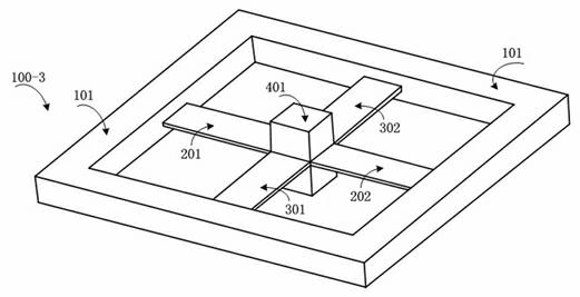
[0036] Such as figure 1 As shown, the present invention adopts the frame type vibration angular rate sensor of swinging mass block to comprise external frame structure 101, swinging mass block 401, driving arm I 201, driving arm II 202, sensitive arm I 301 and sensitive arm II 302, driving arm I 201 The size of the driving arm II 202 is the same, the size of the sensitive arm I 301 and the sensitive arm II 302 are the same, and both adopt a thin sheet structure; one end of the driving arm I 201, the driving arm II 202, the sensitive arm I 301 and the sensitive arm II 302 They are respectively connected to the surroundings of the swing mass 401, and a cross structure i...


PUM


Abstract

The invention discloses a framework type vibration angular rate sensor using a swinging mass block, comprising four cantilever thin sheet vibration beams, which are mutually connected through the swinging mass block. The four cantilever beams are divided into two orthometric pairs, and respectively are a driving arm group and a sensitive arm group of the vibration angular rate sensor; an entire vibration system is fixedly connected with an outer framework, and is fixed with a package shell through the outer framework; driving arms generate bending vibration generated under external excitation, so as to cause the mass block to swing; sensitive arms are driven to do twisting vibration through the swinging of the mass block; when an external input rotation angular speed omega exists around a Z shaft, a Coriolis force is generated by swinging the side face of the mass block, so that the sensitive arms generate the bending vibration, and the driving arms are driven to do twisting vibration through the mass block; and the bending vibration of the sensitive arms and the twisting vibration of the driving arms can be detected, so that the external input rotation angular speed omega is measured. Therefore, the functions of the angular rate sensor is realized, so that the traditional single-vibration beam type angular rate sensor has an angular rate measurement error, caused by inter-axial interference and sensitive matrix movement.

Description

technical field [0001] The invention relates to an angular rate sensor, in particular to a frame-type vibration angular rate sensor using a swing mass block, and also relates to a measurement system using the vibration angular rate sensor. Background technique [0002] The vibration angular rate sensor is an inertial sensor for measuring angular rate developed based on the principle of Gothic vibration. In recent years, with the development of micromachining technology, micromechanical vibration angular rate sensors have shown great advantages in the fields of defense and consumer electronics due to their unique characteristics of low power consumption, small size, and low cost. It is widely used in automotive electronics (such as anti-roll system, anti-skid control and electronic stability control, etc.), consumer electronics (such as camera stabilization, tablet PC and virtual control, etc.), attitude control (such as robot applications and model aircraft applications), et...

Claims


Application Information

Patent Timeline
IPC IPC(8): G01P3/02
Inventor 刘宇刘申欧毅吴英刘利熊文激刘聪
Owner CHONGQING UNIV OF POSTS & TELECOMM
Why Eureka
Try Eureka