
Cutting blades for cutting tools

A technology for cutting blades, cutting tools, applied in the direction of cutting blades, knives for lathes, manufacturing tools, etc., capable of solving problems such as poor chip formation

Active Publication Date: 2016-03-23
CERATIZIT AUSTRIA GES
View PDF5 Cites 0 Cited by
  • Summary
  • Abstract
  • Description
  • Claims
  • Application Information

AI Technical Summary

Problems solved by technology

Due to this structure, cutting inserts are optimized for a specific depth of cut and a specific feed (or a specific feed rate), and chip formation is poor outside the optimized range for the application

Method used


Image

  • Cutting blades for cutting tools
  • Cutting blades for cutting tools
  • Cutting blades for cutting tools

Examples


Embodiment Construction

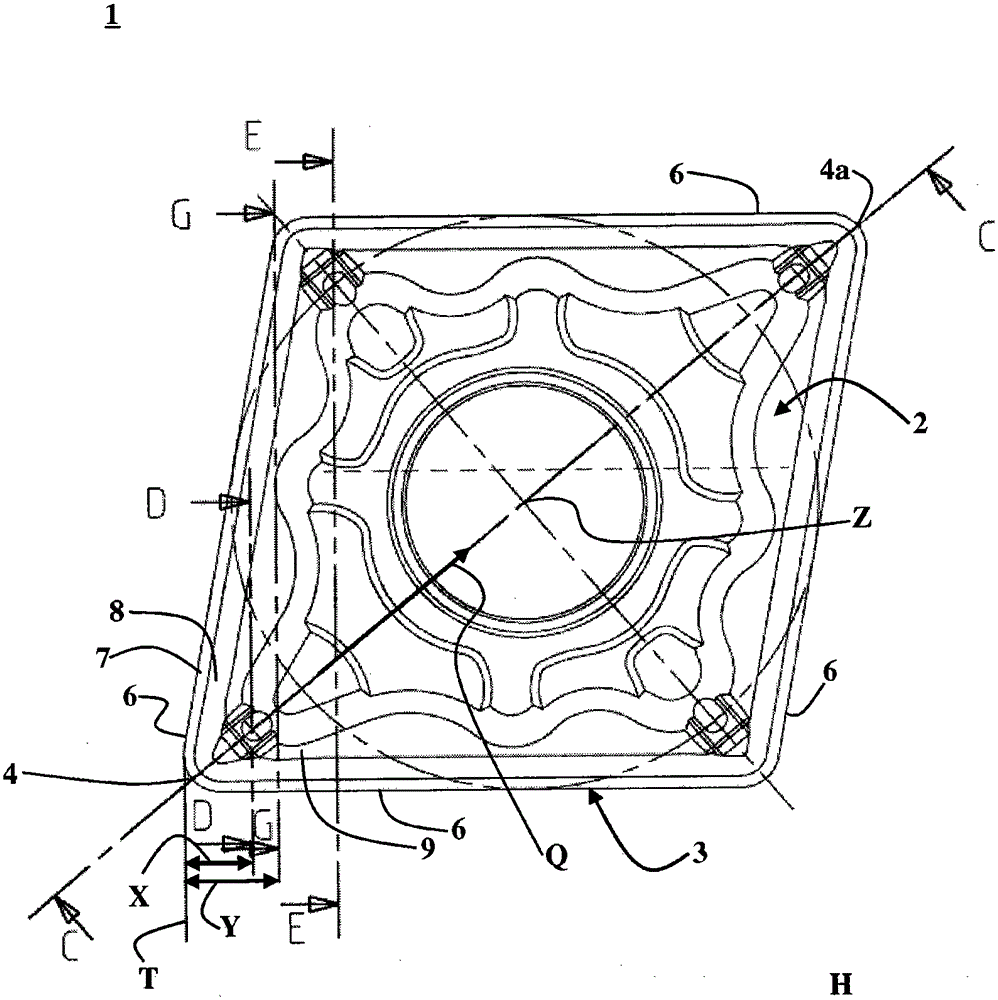
[0031] An exemplary embodiment is described below with reference to the accompanying drawings. figure 1 Shown is a plan view of a cutting blade -1- according to an embodiment. The cutting blade - 1 - according to the exemplary embodiment is designed as an indexable blade. Cutting blade-1-has a top surface-2-( figure 1 shown) and the bottom surface arranged on the rear side (not shown) of the cutting blade -1-. It should be noted that the use of the references "bottom" and "top" faces assumes a certain orientation of the cutting blade, which orientation has been chosen to enable a better understanding of the following description and does not represent a limitation. In this case, the "bottom" face can of course also be arranged to the side or above the "top" face, depending on the orientation of the cutting blade.

[0032] In an exemplary embodiment, the bottom surface is designed in the same way as the top surface -2- and is arranged generally (except for the corresponding ...


PUM


Abstract

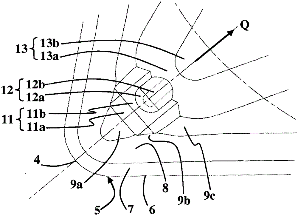
The invention provides a cutting blade (1) for a cutting tool. On the radial direction Q extending from the chamfer (4) to the center Z of the cutting blade (1) in the main plane H, the following items are formed in the following order: inclined rake face (8); chip shape bottom layer (9; 9a, 9b, 9c) adjoining said rake face; a first chip shape (11) adjoining said chip shape bottom layer and having a first surface (11a) rising relative to said chip shape bottom layer, and adjoining a first flat portion (11b) of said first surface (11a); a second chip shape (12) having a second surface (12a) rising relative to said first flat portion (11b), and adjacent to said first flat portion (11b); a second flat portion (12b) of said second surface (12a); and a third chip shape (13) having a third surface (13a) rising relative to said second flat portion (12b), and adjacent to said second flat portion (12b); The third smooth portion (13b) of the third surface (13a).

Description

technical field [0001] The invention relates to a cutting blade of a cutting tool for machining workpieces. Background technique [0002] Cutting blades of cutting tools for machining workpieces are especially useful for machining metal workpieces by turning. It is known to configure such cutting inserts as indexable inserts or as indexable turning inserts, which have multiple chamfers and cutting edges which can be used in succession, for example, after the originally used chamfer or cutting edge has worn away. Cutting corners and cutting edges. In this case, the cutting blade may be configured such that both the top (or upper side) and the bottom (or underside) of the cutting blade are available for material processing. Known cutting blades generally have a geometry in which the top and bottom surfaces are constructed in the same way, and in particular have a cutting edge and a chip shape for deflecting and breaking off cut-off chips of material. [0003] In this case, ...

Claims


Application Information

Patent Timeline
Patent Type & Authority Patents(China)
IPC IPC(8): B23B27/22B23B27/14
CPCB23B27/143B23B2200/081B23B2200/085B23B2200/201B23B2200/321Y10T407/24Y10T82/25Y10T407/23Y10T407/235
Inventor 乌韦·施莱因科弗瑞摩斯·文图里尼
Owner CERATIZIT AUSTRIA GES
Learn More