
Double-sided indexable turning inserts

A turning and insert technology, applied in the field of double-sided indexable turning inserts, which can solve problems such as blunt cutting

Active Publication Date: 2017-08-08
SANDVIK INTELLECTUAL PROPERTY AB
View PDF7 Cites 0 Cited by
  • Summary
  • Abstract
  • Description
  • Claims
  • Application Information

AI Technical Summary

Problems solved by technology

However, a disturbing disadvantage of known turning inserts is that the nose edge and the two main edges, which together form the main cutting edge, have a negative cutting geometry because they are formed on the chip surface and the clearance surface In between, the chip surface and the clearance surface form an angle of 90° with each other, that is, the wedge angle of the cutting edge along the main cutting edge reaches 90° in its entirety
Although in practice this means that the main cutting edge becomes stronger, but on the other hand has a significantly duller cutting edge than a cutting edge with a positive cutting geometry

Method used


Image

  • Double-sided indexable turning inserts
  • Double-sided indexable turning inserts
  • Double-sided indexable turning inserts

Examples


Embodiment Construction

[0047] Detailed description of a preferred embodiment of the turning insert according to the invention

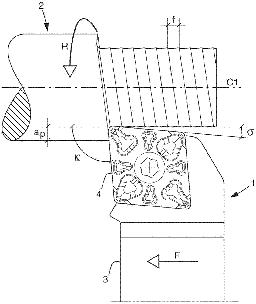
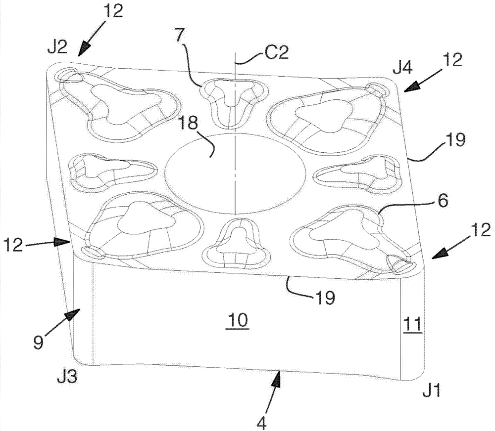
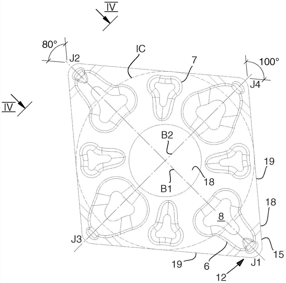
[0048] exist Figure 2 to Figure 4 , it can be seen that the turning insert 4 has a polygonal basic shape and comprises a pair of opposing upper and lower sides generally indicated by 5a and 5b, respectively. The turning insert is double-sided, so that the upper and lower sides are identical. For this reason, only the upper side 5a will be described in detail below.

[0049] In this case, in the upper side 5a, a plurality of mutually spaced platforms 6, 7 are comprised, said platforms individually comprising a flat surface 8, when the turning insert is turned upside down and applied into a seat in the tool holder 3 , the flat platform 8 serves as a support surface. Out of a total of eight lands, four lands, land 6 are located in the region of the corners of the turning insert, while land 7 is placed approximately in the middle between two corner lands 6 . All bearing ...


PUM


Abstract

The invention relates to a double-sided indexable turning insert having a polygonal basic shape and comprising a plurality of corners, peripheral clearance surfaces and identical upper and lower sides comprising bearing surfaces lying in reference planes parallel to each other and to the neutral plane, which is located midway between the reference planes, and the clearance plane extends at right angles towards the neutral plane. There are main cutting edges along the upper and lower sides, including a nose edge at the corner and two main edges, the main edges converge towards the nose edge and are located on the front face inclined with respect to the neutral plane, the main edge transitions to a secondary cutting edge, which is parallel to the A neutral plane extends and separates each pair of main cutting edges along the same side of the turning insert, the chip-guiding guide surface being located inboard of the chip face of the cutting edge. The main cutting edge has a generally positive geometric shape, and the wedge angle of the cutting edge between the chip face and the clearance face is an acute angle along the nose edge and any section of the two main edges. The main cutting edge becomes easy to cut and generates chips that can be guided in a discreet but noticeable manner by the guide surface located on the inside.

Description

technical field [0001] The invention relates to a double-sided indexable turning insert having a polygonal basic shape comprising a plurality of corners, a peripheral clearance surface and identical upper and lower sides comprising: a flat support surface, the flat bearing surface lies in reference planes, the reference planes are parallel to each other and parallel to the neutral plane, the neutral plane is in the middle between the reference planes, and the clearance surface is at right angles towards the center a plurality of main cutting edges formed along the upper side and the lower side, and separately including a nose edge located in the corner and two main edges facing the nose The edges converge and deviate relative to the bisector, wherein the nose edge is formed between the front chip portion surface and the convex portion of the clearance surface and thus has an arcuate cutting edge line, while the main edge is formed in the lateral chip portion between the flat ...

Claims


Application Information

Patent Timeline
Patent Type & Authority Patents(China)
IPC IPC(8): B23B27/16
CPCB23B27/143B23B2200/081B23B2200/321Y10T407/235B23B27/16B23B27/22B23B27/1651
Inventor 罗尼·洛夫马茨·谢尔曼
Owner SANDVIK INTELLECTUAL PROPERTY AB
Learn More