Drive mechanism for a drug delivery device

a technology of driving mechanism and drug delivery device, which is applied in the direction of intravenous device, other medical devices, infusion syringes, etc., can solve the problems of physical infirmity, axial shift of piston rod, and inability to adjust the axial rotation of piston rod, so as to facilitate clearance and manufacturing tolerance elimination, and simplify the general device handling. , the effect of facilitating the elimination of manufacturing tolerances

Inactive Publication Date: 2012-03-22
SANOFI AVENTIS DEUT GMBH
View PDF11 Cites 10 Cited by
  • Summary
  • Abstract
  • Description
  • Claims
  • Application Information

AI Technical Summary

Benefits of technology

[0013]It is therefore an object of the present invention to provide a drive mechanism for a drug delivery device featuring improved and facilitated clearance and manufacturing tolerance elimination. It is a further object of the invention to redundantize a priming procedure to be conducted by the end user. The invention further focuses on improvements related to patient safety and intends to simplify the general device handling. It is a further object of the invention, to provide a drive mechanism for a drug delivery device with clearance eliminating means being inexpensive to produce and being easy to assemble. Finally, it is an object of the invention to provide a method of eliminating clearance in a drive mechanism of a drug delivery device.SUMMARY

Problems solved by technology

For instance in case of those with diabetes, many users will be physically infirm and may also have impaired vision.
Since the generation of an electromagnetic field requires a supply of electric energy, such a solution is generally not applicable to drug delivery devices of pen-injector type.
These known solutions feature the common drawback, that for elimination of axial clearance between piston rod and piston, the piston rod has to be axially shifted.
Such axial displacement of the piston rod for the purpose of clearance elimination is regarded as disadvantageous, because it typically involves a respective actuation of dose setting or dose dispensing means by the user.

Method used


Image

  • Drive mechanism for a drug delivery device
  • Drive mechanism for a drug delivery device
  • Drive mechanism for a drug delivery device

Examples


Embodiment Construction

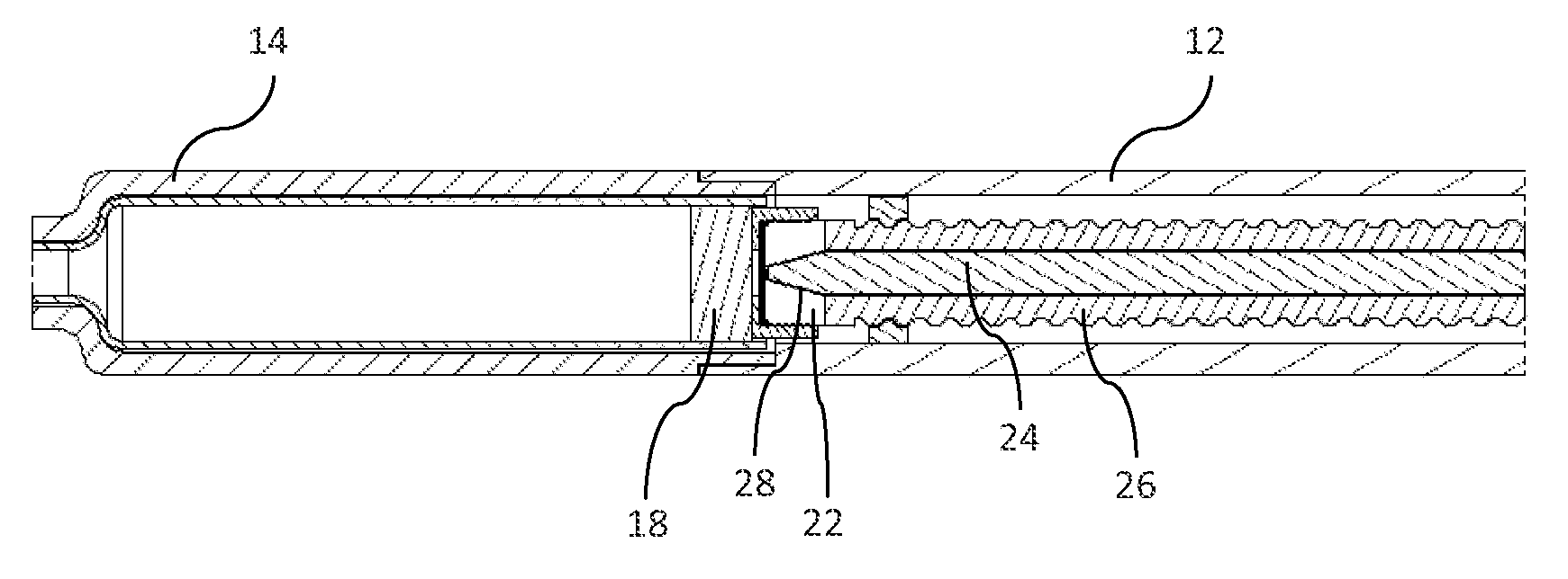
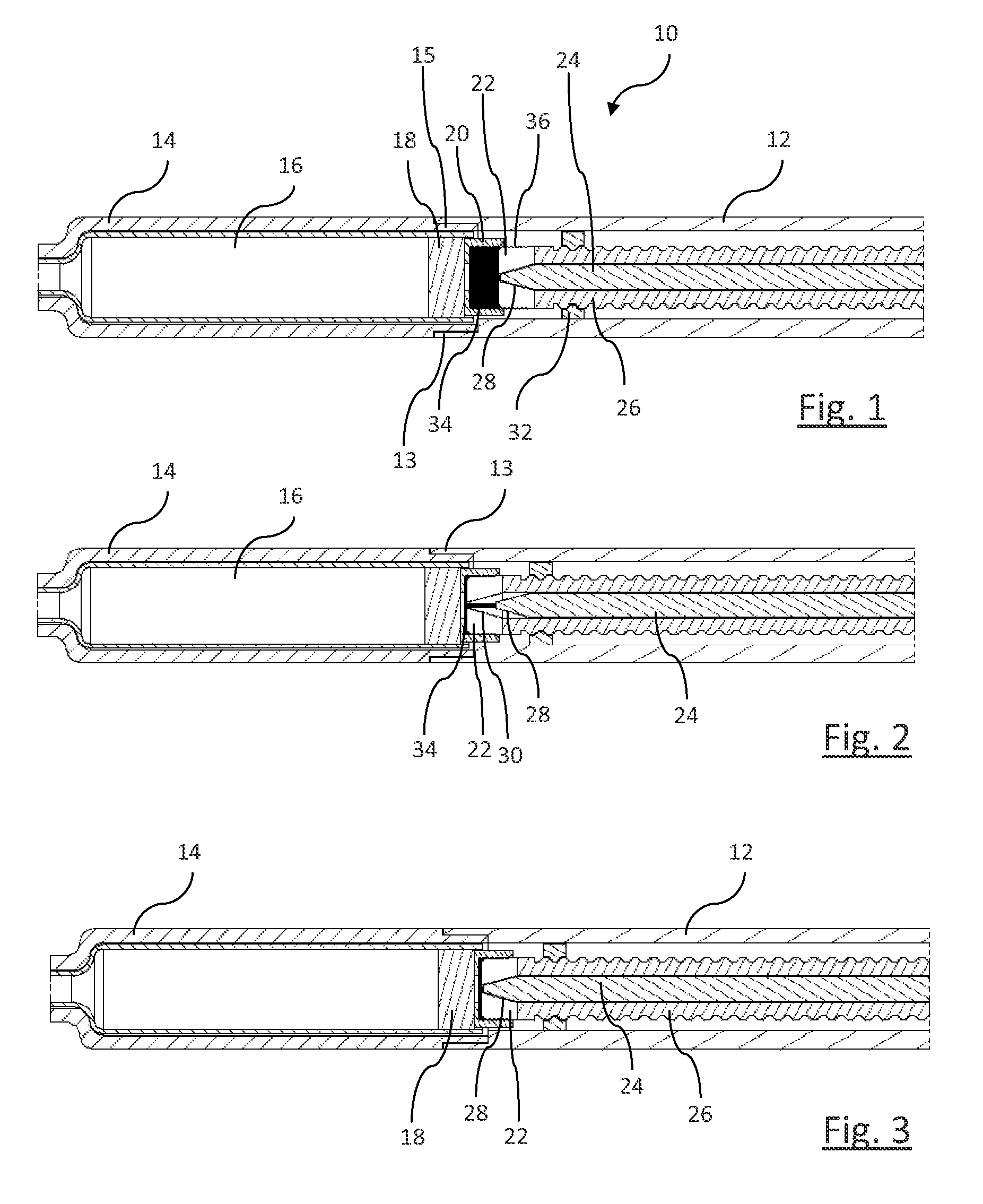
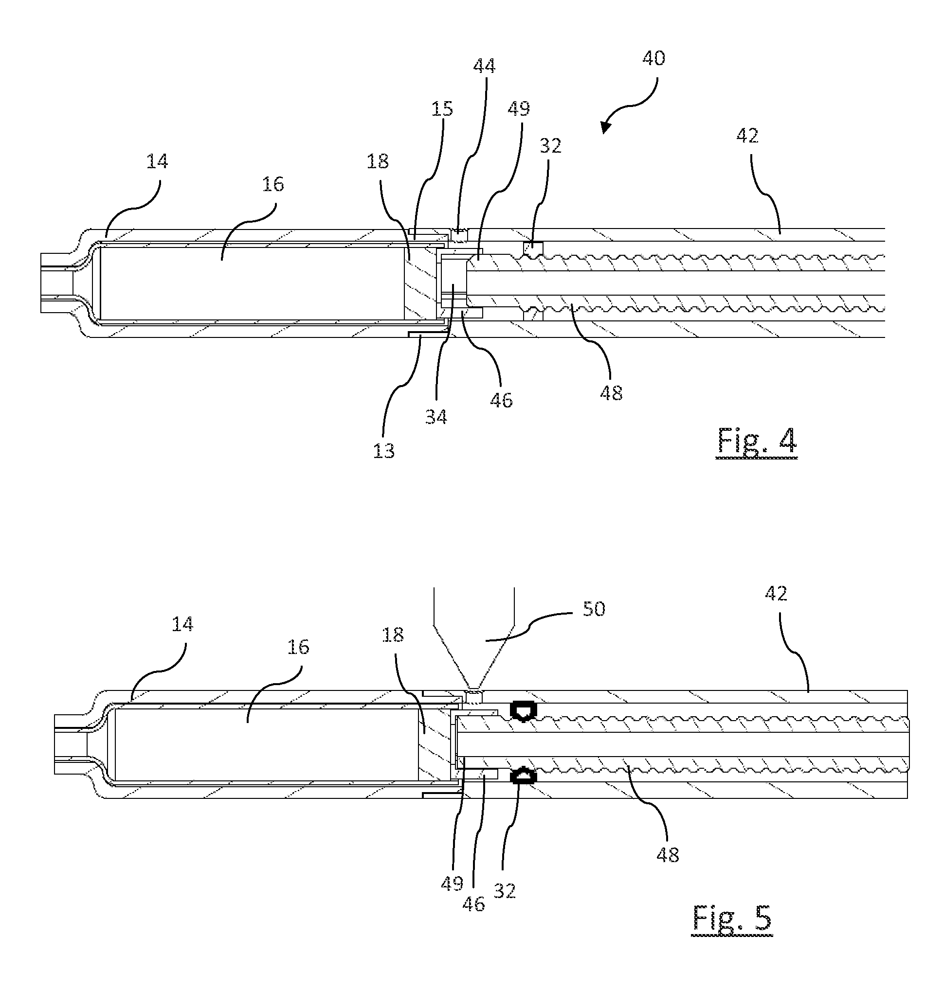
[0142]In the embodiment according to FIGS. 1 to 3 the drive mechanism of a drug delivery device 10 is illustrated in a first embodiment. The mechanism comprises a cartridge 16 filled with a medicinal product to be dose-wise dispensed. The cartridge 16 is mounted in a cartridge holder 14 having a stepped down neck portion towards its distal end, which, in the embodiment according to FIGS. 1 to 3 is located on the left hand side.

[0143]In proximal direction, directed to the right hand side in FIGS. 1 to 3, the cartridge 16 has an axially slideably arranged piston 18, which—under an impact of a distal movement of a driven piston rod 26—is stepwise moved in distal direction for the purpose of expelling or purging an exact and precise amount of the medicinal product contained in the cartridge. The piston rod 26 is radially secured by means of a mount 32. It is axially displaceable by means of a not further illustrated dose dispensing or drive mechanism. The cartridge holder 14 is further ...


PUM

PropertyMeasurementUnit
molecular weightaaaaaaaaaa
retention forceaaaaaaaaaa
axial forceaaaaaaaaaa

Abstract

The present invention relates to a drive mechanism for a drug delivery device as well as to a drug delivery device for dispensing of a dose of a medicinal product, wherein the drive mechanism comprises:a holder for a product-containing cartridge, the cartridge having a piston slidably arranged therein in an axial direction,a piston rod to be operably engaged with the cartridge's piston for dispensing of a dose of the medicinal product,at least one adjusting member slidably arranged in axial direction relative to the piston and / or relative to the piston rod for eliminating axial clearance between the piston and the piston rod,an interlock means adapted to interact with the adjusting member for mutually locking in position the piston and the piston rod irrespective of the relative distance between piston and piston rod.

Description

CROSS REFERENCE TO RELATED APPLICATIONS[0001]The present application is a U.S. National Phase Application pursuant to 35 U.S.C. §371 of International Application No. PCT / EP2010 / 055140 filed Apr. 20, 2010, which claims priority to _European Patent Application No. 09005996.5 filed on Apr. 30, 2009. The entire disclosure contents of these applications are herewith incorporated by reference into the present application.FIELD OF THE INVENTION[0002]This invention relates to a drive mechanism for a drug delivery device that allows a user to select single or multiple doses of an injectable medicinal product and to dispense the set dosage of the product and to apply said product to a patient, preferably by injection. In particular, the present invention relates to such devices, which are handled by the patients themselves.BACKGROUND[0003]Drug delivery devices allowing for multiple dosing of a required dosage of a liquid medicinal product, such as liquid drugs, and further providing administr...

Claims


Application Information

Patent Timeline
Patent Type & Authority Applications(United States)
IPC IPC(8): A61M5/315
CPCA61M5/3146A61M5/31515A61M5/24A61M2207/00Y10T29/49826A61M2005/2407A61M5/31551A61M5/3158
Inventor FORSTREUTER, AXELHELMER, MICHAELMATTHIAS, CLAUDIANOBER, PETERSHAHBAZFAR, REZASCHAFER, BENJAMINZEIMETZ, LEODASBACH, UWE
Owner SANOFI AVENTIS DEUT GMBH
Why Eureka
Try Eureka