Anti-skid stud

An anti-skid pin and plug-in technology, applied in the direction of tire tread/tread pattern, wheels, tire parts, etc., can solve the problems of not providing road surface skid resistance, unreasonable cost, etc., to improve side stability and better road surface. The effect of anti-skid

Inactive Publication Date: 2012-09-12
SITEK SPIKES +1
View PDF9 Cites 3 Cited by
  • Summary
  • Abstract
  • Description
  • Claims
  • Application Information

AI Technical Summary

Problems solved by technology

Here too the problem is that exact skid orientation is required
A heptagonal cross-section was also proposed, but it was then close to a circular cross-section and did not provide substantially better road skid resistance compared to it, so that the higher costs required for production were not justified

Method used


Image

  • Anti-skid stud
  • Anti-skid stud
  • Anti-skid stud

Examples


Embodiment Construction

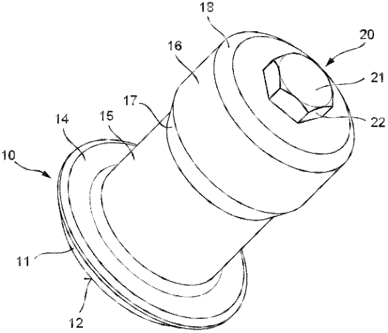
[0024] figure 1 A cleat is shown with a bearing part 10 manufactured as a metal casting, in particular an aluminum casting.

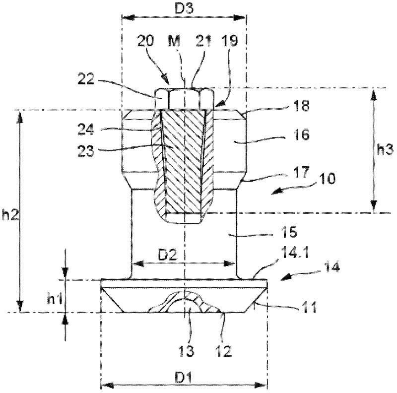
[0025] Such as figure 2 As can be clearly seen, the bearing part 10 has a flange part 14 designed as a fastening foot, which forms a lower, flat bearing surface 12 in which, for reasons of weight reduction, recesses 13 are deep-cut.

[0026] An annular circumferential bevel 11 adjoins at an angle to the bearing surface 12 . This bevel 11 transitions via a circular cross-section into a shoulder 14.1, which is oriented perpendicularly to the central longitudinal axis M of the anti-skid pin.

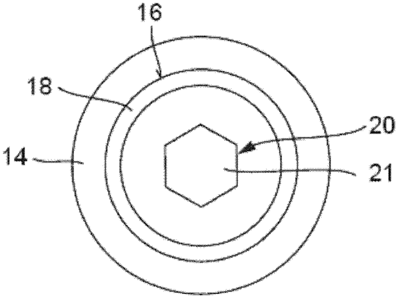
[0027] Such as image 3 It is shown that the shoulder 14 . 1 runs annularly around the central longitudinal axis M . The flange part 14 itself is configured as a frusto-conical shape and has a first largest diameter D1 (eg ≧7.5 mm, currently 8.2 mm). In the region of the shoulder 14 . 1 the holder 15 is molded onto the flange part 14 . The holding portion 15 h...


PUM


Abstract

The invention relates to an anti-skid stud for a tyre having a supporting part (10) and an insert (20) which is secured thereto, wherein the supporting part (10) has a flange section (14) to which a securing section (15), into which a receptacle (19) is integrally formed, is connected, wherein the insert (20) is inserted into the receptacle (19) and projects with a head (22) out of the receptacle (19). In such anti-skid studs, particularly good grip is achieved which remains the same independently of the positional orientation in the tyre by virtue of the fact that the head (22) of the insert (20) has a hexagonal cross section at least in certain areas.

Description

technical field [0001] The invention relates to an anti-skid pin for tires, having a support part and an insert held thereon, wherein the support part has a flange part, to which the retaining part is connected, in which a receptacle is formed , wherein the insert is inserted into the receptacle and protrudes from the receptacle by means of the head. Background technique [0002] Such an anti-skid pin is known from DE 19 03 668 . A bearing part is used here, which has a flange part as a fastening foot. A cylindrical holder is integrally formed on the fastening foot. Receptacles, preferably hard metal pins, are held in the holder in the form of blind holes in which an insert made of hard plastic is held. The insert protrudes from the receptacle with a head, wherein the head can be square, circular or triangular in cross-section. The head forms a functional element which, during winter operation, is inserted into the snow or ice layer on the roadway in order to achieve bet...

Claims


Application Information

Patent Timeline
Patent Type & Authority Applications(China)
IPC IPC(8): B60C11/16
CPCB60C11/1643B60C11/1675B60C11/1681Y10T152/10279
Inventor 弗雷德里克·米歇尔·杰·庞斯塞巴斯蒂安·莫林赛维尔·塞巴斯蒂安·贝努瓦·弗雷蓬斯特凡·罗仕
Owner SITEK SPIKES
Why Eureka
Try Eureka