Clamping devices and brackets with clamping devices

A technology of clamping devices and tensioning parts, applied in the field of clamping devices, can solve problems such as easy failure, complexity, and wear, and achieve the effects of good anti-slip resistance, simple structure, and cost reduction

Inactive Publication Date: 2012-02-15
KRINNER INNOVATION
View PDF4 Cites 0 Cited by
  • Summary
  • Abstract
  • Description
  • Claims
  • Application Information

AI Technical Summary

Problems solved by technology

But the price it pays for this is that the structure is quite complex, expensive and prone to failure
[0007] In addition, all these clamping devices or brackets with clamping devices have in common that they are now designed and fixedly combined in the bracket due to the inclusion of ratchets or other means, or can be plugged in if necessary, as in DE20320092U1 The tensioning rods, as well as the inclusion of complex stop devices, have opted for a rather complex and therefore expensive construction which, in addition, is not completely trouble-free due to wear, especially in the event of contamination

Method used


Image

  • Clamping devices and brackets with clamping devices
  • Clamping devices and brackets with clamping devices
  • Clamping devices and brackets with clamping devices

Examples


Embodiment Construction

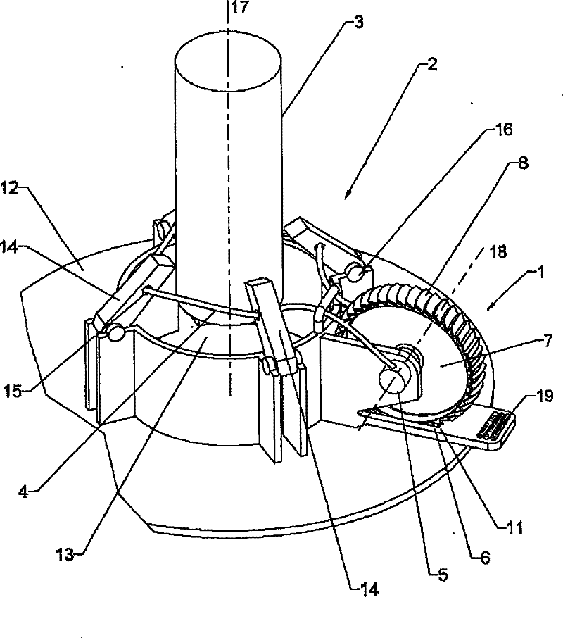
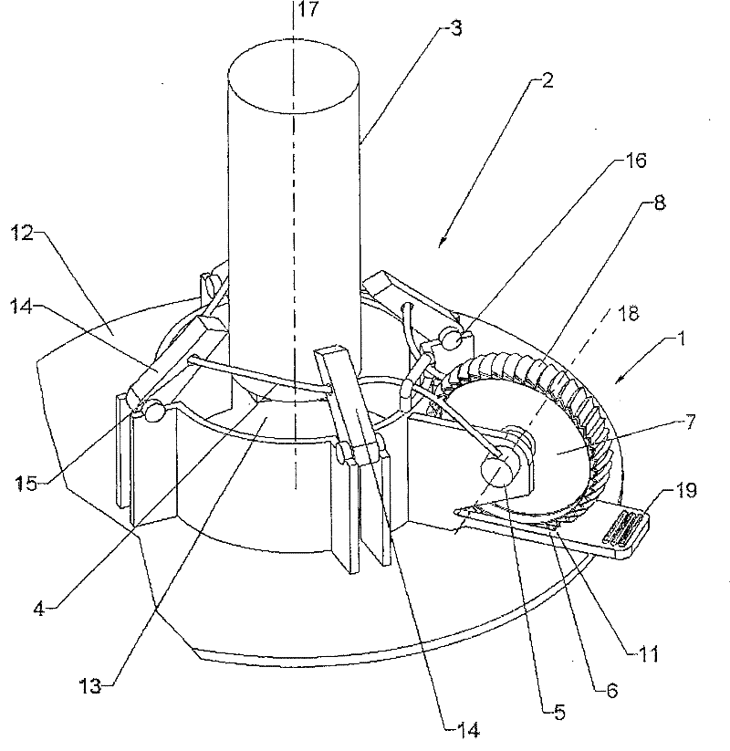
[0034] figure 1 Represents the bracket 2 for clamping a rod 3, comprising a base 12, a mounting area 13 and fixing elements 14, which can be moved around an axis of rotation 16 toward the The support axis of symmetry 17 moves. The fastening elements 14 are movable by means of the flexible force transmission element 4 , preferably a cable, which slides through all the fastening elements 14 in the guide bore 15 .

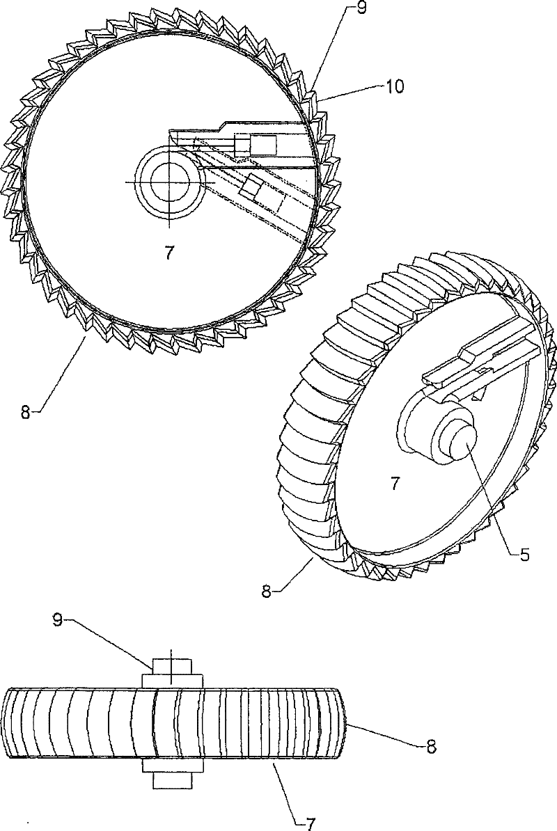
[0035] To clamp the rod-shaped part 3 , the flexible force-transmitting element 4 is tensioned in the clamping device 1 attached to the support 2 . The clamping device 1 consists of a rotatable clamping part 5 on which the flexible force transmission part 4 is wound for clamping the fastening element 14 . For actuating the tensioning element, a drive wheel 7 is provided, which is connected in a rotationally fixed manner to the tensioning element 5 with the same axis of rotation 18, and can also be integrally formed on the tensioning element if necessary. The drive ...


PUM


Abstract

The tensioning device on a stand (2) for tensioning a rod-form component (3), especially a Christmas tree, includes a force transmission element (4) which by one end is wound on a rotatable tensioning component (5), wherein for operating the rotatable tensioning component, a drive wheel (7) is provided, the diameter of which is a multiple of the diameter of the rotatable tensioning component. The drive wheel shares with the rotatable tensioning component a common axis (18) and is connected to it in a torsionally fixed manner. An independent claim is included for a stand for tensioning a rod-form element, especially a Christmas tree, equipped with the proposed tensioning device.

Description

technical field [0001] The invention relates to a clamping device for clamping a rod, especially a Christmas tree, on a stand and a stand with such a clamping device for clamping a rod, especially a Christmas tree. Background technique [0002] Various supports are known, in particular for clamping Christmas trees, in which a pivotable fastening element is pivoted by means of one or more tension-capable flexible force transmission elements and thus clamps the Christmas tree around. The flexible power transmission member is usually a steel cable or composed of multiple steel cables. It is guided through a guide hole in the fastening element, generally above its axis of rotation. The effective length of the at least one steel cable is shortened by the clamping device on the support so that the fixing element is swiveled inwards in the direction of bearing against the rod. [0003] DE3932473C2, DE10220879A1, DE3932432C2 and DE20105005U1 disclose some relevant examples. Here,...

Claims


Application Information

Patent Timeline
Patent Type & Authority Patents(China)
IPC IPC(8): F16M13/00A47G33/12
CPCA47G33/1213Y10T24/2117Y10T24/2147
Inventor 冈瑟·特纳
Owner KRINNER INNOVATION
Why Eureka
Try Eureka