Method for manufacturing telescopic shaft and telescopic shaft manufactured by same

A manufacturing method and telescopic shaft technology, which is applied to steering control, couplings, steering control, etc. installed on the vehicle, and can solve the problems of sliding resistance fluctuations, high torque of the intermediate shaft 16, difficulty for lubricating oil to reach the pressing concave surface 611, etc. question

Active Publication Date: 2012-09-12
NSK LTD
View PDF4 Cites 11 Cited by
  • Summary
  • Abstract
  • Description
  • Claims
  • Application Information

AI Technical Summary

Problems solved by technology

[0012] In this way, when the female shaft 16B is slid with respect to the male shaft 16A, the tooth surface 412 near the tooth top 411D at the D-D cross-sectional position of the cog groove 41 of the female shaft 16B sinks into the covering portion 61 , causing a disadvantage in that the sliding resistance fluctuates.
Furthermore, since the stepped surface 612 is formed in the covering portion 61, the lubricating oil filled near the root of the protruding tooth 51 of the male shaft 16A is blocked by the stepped surface 612, so that it is difficult for the lubricating oil to reach the pressing concave surface 611.
[0013] In addition, in the conventional hydraulic power steering system, the torque applied to the intermediate shaft 16 is relatively small, but in the column assist type electric power steering system, the torque applied to the intermediate shaft 16 is relatively large.
Therefore, the deformation of the covering portion 61 of the intermediate shaft 16 becomes large, and the addendum of the female shaft 16B sinks into the covering portion 61 of the dedendum of the male shaft 16A, thereby causing a disadvantage in that the sliding resistance fluctuates.

Method used


Image

  • Method for manufacturing telescopic shaft and telescopic shaft manufactured by same
  • Method for manufacturing telescopic shaft and telescopic shaft manufactured by same
  • Method for manufacturing telescopic shaft and telescopic shaft manufactured by same

Examples


Embodiment 1

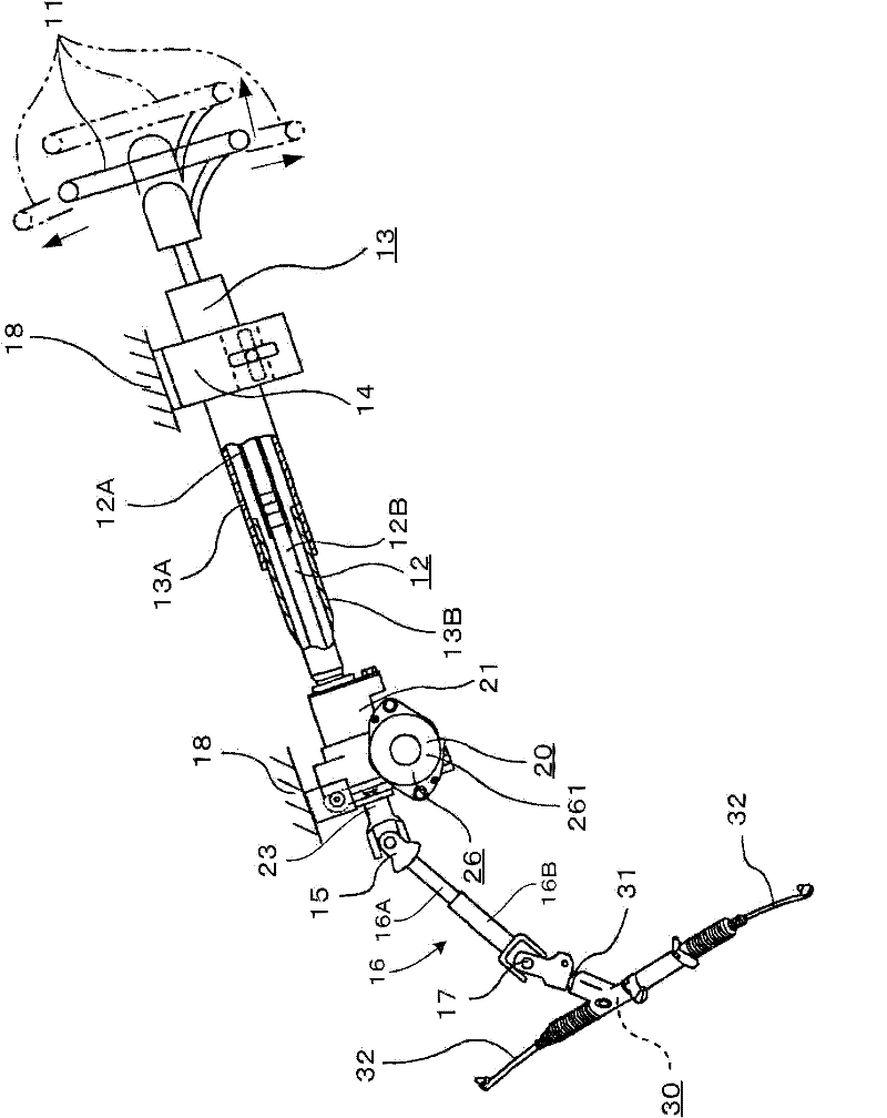
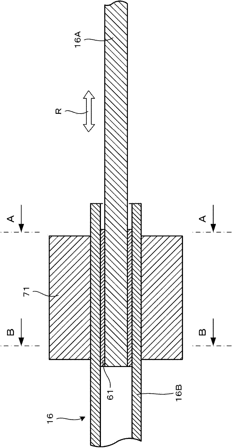
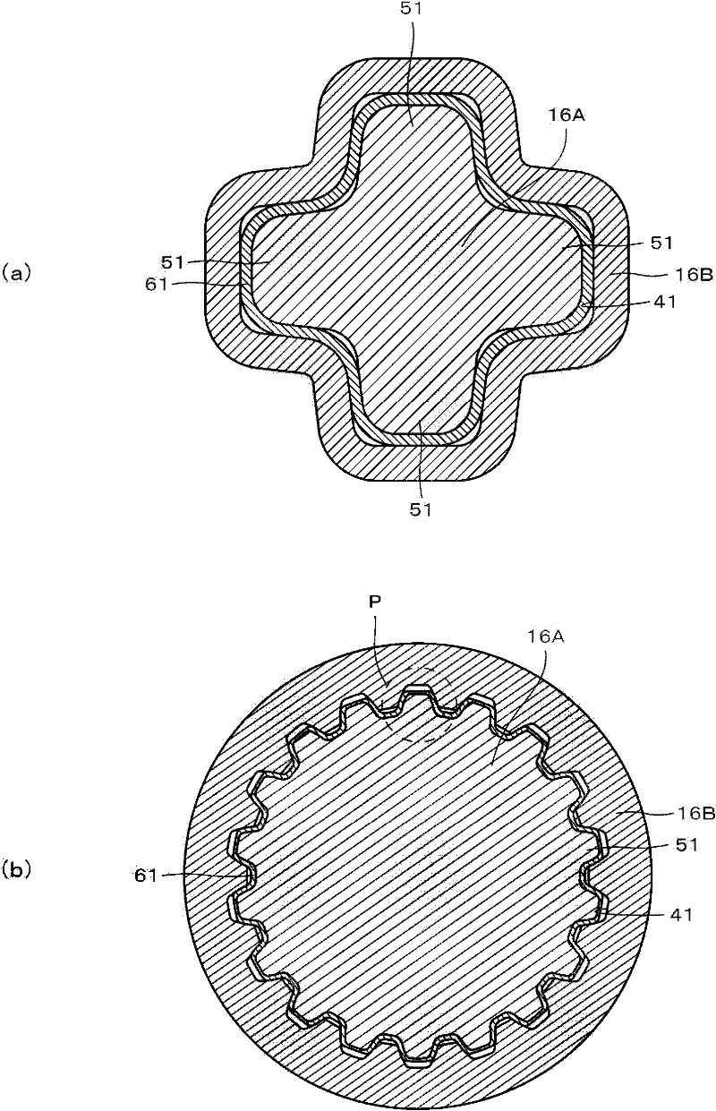
[0048] Hereinafter, embodiments of the present invention will be described based on the drawings. figure 1 It is a side view showing the whole steering device having a telescoping shaft according to the present invention with a part cut away, showing an embodiment applicable to an electric power steering device having a control auxiliary part. figure 2 It is a longitudinal cross-sectional view showing the manufacturing process of the telescopic shaft according to the first embodiment of the present invention. image 3 express figure 2 The enlarged cross-sectional view of image 3 (a) is an enlarged sectional view showing a telescoping shaft covered with a sleeve, image 3 (b) is an enlarged cross-sectional view showing the telescopic shaft of the coated portion.

[0049] Figure 4 It is a perspective view showing the male shaft of the telescopic shaft in Embodiment 1 of the present invention, Figure 5 It shows the manufacturing process of the telescopic shaft of Examp...

Embodiment 2

[0086] Next, Example 2 of the present invention will be described. Figure 10 It is an enlarged cross-sectional view showing the telescopic shaft of Embodiment 2 of the present invention, which is the same as that of Embodiment 1. image 3 (b) equivalent graph, Figure 11 yes Figure 10 The enlarged cross-sectional view of the R portion, which is the same as that of Example 1 Figure 5 (b) equivalent graph, Figure 12 yes Figure 11 The enlarged cross-sectional view of part S of . In the following description, only structural parts different from those of the above-mentioned embodiments will be described, and repeated descriptions will be omitted. In addition, the same symbols are attached to the same members and will be described. Example 2 is an example in which the covering portion 61 is bonded to the tooth surface of the protruding bar tooth 51 with an adhesive.

[0087] That is, if Figure 10 to Figure 12 As shown, for the telescopic shaft of Example 2, the female...

Embodiment 3

[0098] Next, Example 3 of the present invention will be described. Figure 13 It is an enlarged cross-sectional view of the meshing portion of the telescopic shaft according to the third embodiment of the present invention. In the following description, only structural parts different from those of the above-mentioned embodiments will be described, and repeated descriptions will be omitted. In addition, the same symbols are attached to the same members and will be described. Embodiment 3 is an example in which a wedge-shaped gap is formed at the meshing portion between the tooth surface of the protruding rack tooth 51 and the tooth surface of the tooth groove 41 toward both ends in the tooth height direction.

[0099] That is, if Figure 13 As shown, for the telescopic shaft of Embodiment 3, the convex tooth 51 of the male shaft 16A is covered with a material that reduces the sliding resistance between the convex tooth 51 and the tooth groove 41 of the female shaft (female s...


PUM


Abstract

To provide a method for manufacturing a telescopic shaft having a coated section which reduces sliding resistance, the telescopic shaft being configured in such a manner that a variation in the sliding resistance depending on the position of sliding of the telescopic shaft is reduced and that lubricating oil exhibits satisfactory lubricating performance. [Solution] Clearance sections (613) are formed in a coated section (61) so that portions of the tooth flanks (412) of the tooth grooves (41) of a female shaft (16B), the portions being located near the tooth tops (411A) between the tooth grooves (41), do not come into contact with portions of the coated section (61) on the tooth flanks of protruding teeth (51), the portions being located near the roots of the protruding teeth (51). The amount of plastic deformation obtained by compressing the coated section (61) by subjecting an intermediate shaft (16) to break-in operation is in the range from 1 micrometer to 10 micrometers. This means that the depth (a1) of the clearance sections (613) before the coated section (61) is plastically deformed by compressive stress applied thereto is preferably 10 micrometers or greater. Even after the coated section (61) is plastically deformed, the clearance sections (613) are maintained recessed from a plastically deformable surface (614) by a depth (a2).

Description

technical field [0001] The present invention relates to a method for manufacturing a telescopic shaft and a telescopic shaft manufactured by the manufacturing method. The telescopic shaft is particularly a telescopic shaft capable of transmitting rotational torque and relatively sliding in the axial direction, such as an intermediate shaft and a steering shaft. Background technique [0002] In a steering device, a telescopic shaft such as a spline shaft coupled so as to be capable of transmitting rotational torque and relatively slidable in the axial direction is incorporated into an intermediate shaft, a steering shaft, and the like. That is, when fastening the universal joint to the pinion shaft that meshes with the rack shaft of the steering gear, the intermediate shaft is fastened to fit the pinion shaft from a temporarily contracted state, or to absorb contact with the vehicle body. The relative displacement between the frames requires a telescoping function. [0003] ...

Claims


Application Information

Patent Timeline
Patent Type & Authority Applications(China)
IPC IPC(8): B62D1/185
CPCF16D3/06B62D1/20F16D2300/10
Inventor 黑川祥史稻木奖
Owner NSK LTD
Why Eureka
Try Eureka