Powder compression molding method and mould thereof

A technology of die-casting molding and powder, which is applied in the direction of material molding presses, presses, manufacturing tools, etc., and can solve problems such as incompleteness and inability to form moldings

Inactive Publication Date: 2012-09-19
SHUOEN TECH
View PDF5 Cites 1 Cited by
  • Summary
  • Abstract
  • Description
  • Claims
  • Application Information

AI Technical Summary

Problems solved by technology

[0005] The invention provides a powder die-casting molding method and a mold used therefor, which respectively compress the protruding part and the base in the finished product shape, so as to avoid the problem that the molding cannot be formed or the molding is incomplete

Method used


Image

  • Powder compression molding method and mould thereof
  • Powder compression molding method and mould thereof
  • Powder compression molding method and mould thereof

Examples


Embodiment Construction

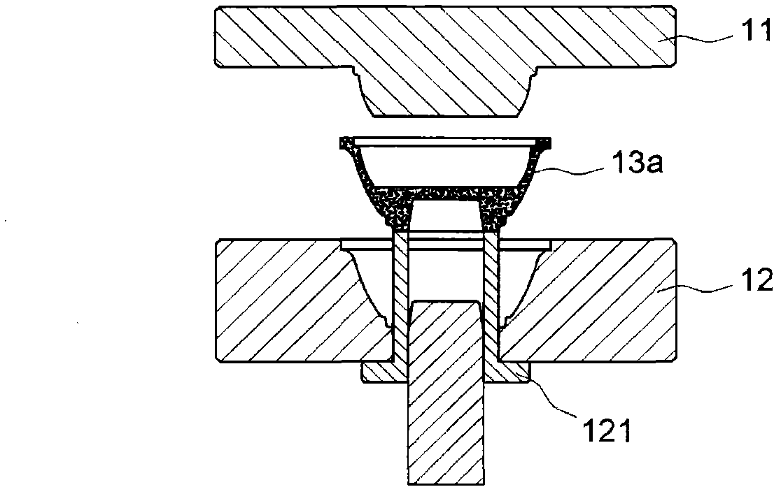
[0040] Please refer to Figure 3a to Figure 3d , to make Figure 2c The finished product 13c having a base 131 and a protruding part 132 is shown as an example, illustrating that the powder die-casting molding method according to an embodiment of the present invention is applied to the die-casting step in which the protruding part of the finished product is facing downward. The method of the present invention includes a first powder filling step, a first mold clamping step and a compression step. The first powder filling step is to close the lower mold female mold core block 33 with the lower mold female mold core template 32 to form a first mold cavity and fill a powder 80 in the first mold cavity, such as Figure 3a shown. Wherein, the recessed depth of the lower die female core block 33 than the lower die female core template 32 is greater than the height of the protruding portion 132 of the finished product, so as to provide the powder filling space required by the protr...


PUM

PropertyMeasurementUnit
Particle sizeaaaaaaaaaa

Abstract

Provided is a powder compression molding method for manufacturing a product with a base and a protruding part, comprising a first filling powder process, a first mould assembly process and a compression process. In the first filling powder process, powder is filled in a first mould groove formed by a lower mould female mould core insert block and a lower mould female mould core template. In the first mould assembly process, an upper mould male mold core and a lower mould female mould core are assembled to confine powder in a mould cavity. In the compression process, powder corresponding with the protruding part and the base are respectively compressed to form products so as to avoid the problem that powder with poor liquidity ca not be compressed for molding or the moulding is not complete. The invention also discloses a mould using the method.

Description

【Technical field】 [0001] The invention relates to a die-casting molding method and a mold used therefor, in particular to a die-casting molding method using powder with poor fluidity as a material and a mold used therefor. 【Background technique】 [0002] Please refer to Figure 1a to Figure 1c , the existing powder die-casting molding method is to fill the powder 13 in the cavity of the lower mold female core template 12, and then squeeze the powder 13 from the upper mold male mold core 11, so that the powder 13 evenly fills the upper mold male mold core 11 The mold cavity after closing the mold with the lower mold female mold core template 12, to form the desired appearance. Finally, the finished product 13a formed by die-casting from the powder 13 is pushed out from the lower mold top block 121 . [0003] However, the powder with poor fluidity cannot flow to other positions in the mold cavity due to the extrusion of the upper die male die core 11, causing the powder 13b t...

Claims


Application Information

Patent Timeline
IPC IPC(8): B22F3/03B30B11/02
Inventor 江中琦胡旭添萧俊旭
Owner SHUOEN TECH
Why Eureka
Try Eureka