Adaptive compensation power-supply apparatus and its drive method

A technology for compensating power supply and driving method, applied to instruments, static indicators, etc., can solve problems such as inconsistency, difference in brightness of display screen, failure to charge voltage to pixel capacitor 12, etc., and achieve the effect of eliminating block defects

Inactive Publication Date: 2008-06-04
CHUNGHWA PICTURE TUBES LTD
View PDF0 Cites 7 Cited by
  • Summary
  • Abstract
  • Description
  • Claims
  • Application Information

AI Technical Summary

Problems solved by technology

However, since the bias power supply of the unity-gain operational amplifier 10 is AVDD, when AVDD is affected by layout traces, impedance effects of trace materials, and the internal impedance of the source IC itself, AVDD attenuates, causing each source IC to output different voltage levels. , then the unity-gain operational amplifier 10 will not be able to charge the pixel capacitor 12 with the most correct voltage, so that color block defects will occur on the panel display screen
Also, multiple switches in the display circuit of the single output end of the thin film transistor liquid crystal display utilize P-channel metal-oxide-semiconductor (PMOS) to achieve the action of the switch, yet there is a parasitic diode 14 in the PMOS itself (its conduction bias is 0.7 volts) across the drain terminal (D) and base terminal (B) of the PMOS, if the voltage difference between the input data voltage (data) and AVDD is greater than the conduction bias of the parasitic diode 14 due to the attenuation of AVDD If the voltage is 0.7 volts, the parasit

Method used


Image

  • Adaptive compensation power-supply apparatus and its drive method
  • Adaptive compensation power-supply apparatus and its drive method
  • Adaptive compensation power-supply apparatus and its drive method

Examples


Embodiment Construction

[0046] The following uses a preferred embodiment to illustrate the adaptive compensation power supply device and its driving method of the present invention.

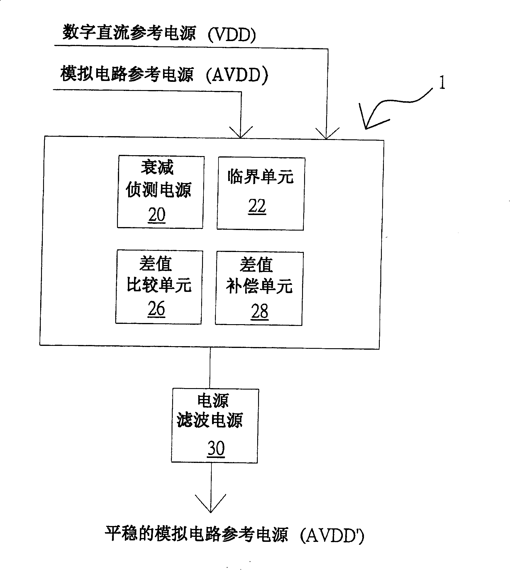
[0047] see image 3, is a schematic diagram of a hardware architecture according to a preferred embodiment of the present invention. As shown in the figure, the adaptive compensation power supply device 1 includes an attenuation detection unit 20, which is used to judge whether the AVDD of the input source ICs is attenuated or not; a critical unit 22, which is electrically connected to the attenuation detection unit 20, for judging Whether the attenuation amplitude of the pulsating DC level of AVDD is a ripple floating or a large attenuation. In one embodiment, a threshold voltage value is set in the threshold unit 22 , and if the AVDD voltage level is lower than the preset threshold voltage value, the adaptive compensation power supply device 1 is activated. On the contrary, if the voltage level of AVDD is not lower ...


PUM


Abstract

The invention relates to an adaptive compensation power device and the driving method, the device comprises two circuit reference powers, an attenuation detecting unit, a difference comparing unit, wherein the attenuation detecting unit is electrically connected and the digital direct current reference power is accepted. A voltage difference and a difference compensation unit are obtained after contrasting the voltages of the analogous circuit reference power and the digital direct current reference power. The invention utilizes a detecting circuit to detect the drift amount of the analogous circuit reference power to the reference position in an analogous source drive, and provides an compensation potential, and outputs a stable direct current voltage as the analogous circuit reference power after compensation to balance the output reference position differences of the every analogous source drives, further eliminates the block defects between the adjacent intervals of a panel.

Description

technical field [0001] The invention relates to a power supply compensation device, in particular to an adaptive compensation power supply device applied to a display. Background technique [0002] Please refer to FIG. 1 , which is a schematic diagram of a bias circuit of a thin film transistor liquid crystal display in the prior art. Generally, the driver IC of a thin film transistor liquid crystal display is directly arranged on the glass, film or tape of the thin film transistor array, and multiple analog source drivers (source ICs, such as S1, S2, and S3 in the figure) are arranged on the On one side of the substrate, the analog gate driver (gateIC, G1 in the figure) is arranged on the other side of the substrate, and the signal connection lines between the drivers are directly laid out on the substrate, and connected with the flexible printed circuit board 2 (Flexible Print Circuit, FPC) connected to receive the signal sent by the external system. As shown in the figu...

Claims


Application Information

Patent Timeline
IPC IPC(8): G09G3/36
Inventor 吕家亿叶志民黄仕泓
Owner CHUNGHWA PICTURE TUBES LTD
Why Eureka
Try Eureka