Electromagnetic door locks for electrical equipment

A technology for electromagnetic door locks and electrical equipment, applied in non-mechanical transmission-operated locks, building locks, buildings, etc., can solve the problems of high material cost and assembly cost, abnormal state of electromagnetic door locks, affecting the final use of products, etc. Reliable operation, reduced parts count, and high availability

Inactive Publication Date: 2016-06-01
ILLINOIS TOOL WORKS INC
View PDF5 Cites 0 Cited by
  • Summary
  • Abstract
  • Description
  • Claims
  • Application Information

AI Technical Summary

Problems solved by technology

But this method needs to add more parts and control lines, which makes the material cost and assembly cost higher; more parts means more failure modes, which reduces the reliability of the product
[0004] In addition, during the transportation of existing electromagnetic door locks (including the transportation of individual door locks and the transportation of electrical equipment equipped with door locks), the electromagnetic door locks will be in an abnormal state due to the bumps in the transportation process, which will affect the quality of the product. end use

Method used


Image

  • Electromagnetic door locks for electrical equipment
  • Electromagnetic door locks for electrical equipment
  • Electromagnetic door locks for electrical equipment

Examples


no. 1 example

[0118] The working process of the first embodiment is as follows:

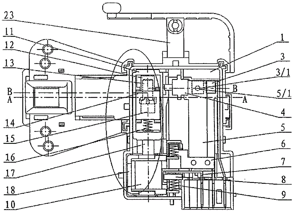
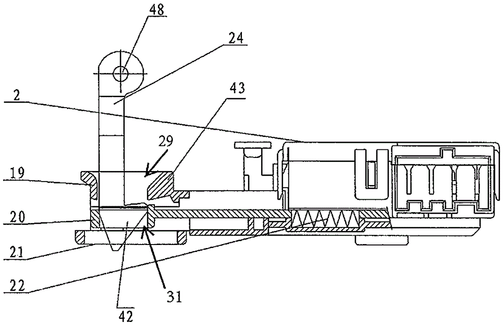
[0119] During normal operation, the door of the electrical equipment is closed, the door hook 24 pushes the slider device 20A to the locked position, the lock hole of the slider device 20A is aligned with the lock device 4A, and the lock device 4A can freely enter and exit the slider lock hole 30; When the door lock receives the driving signal, the electromagnetic coil 10 drives the iron core 17, and drags the refill lock frame 11A to the locked position, where the refill lock frame 11A is separated from the lock block device 4A, and the movable contact of the switch assembly device The dot shrapnel 5 drives the lock block device 4A to move downward due to its own elastic force, the switch is closed, and the electrical equipment can work normally; at the same time, the lock block device 4A enters the slider lock hole 30 of the slider device 20A to fix it, and the slider device 20A Also lock the door hook 24, t...

no. 2 example

[0125] The working process of the second embodiment is as follows:

[0126] During normal operation, such as Figure 13B As shown, the electrical equipment door is closed, and the door hook 24 pushes the slider device 20B to the locked position, and its slider lock hole 30 is aligned with the lock block device 4B), and the lock block device 4B can freely enter and exit; when the door lock receives the driving signal , the electromagnetic coil drives the iron core, drags the refill lock frame 11B to the locked position, and at the same time the lock block device 4B moves downward along the guide chute 28, and the movable contact shrapnel 5 of the switch assembly device also moves downward. The switch is closed, and the electrical equipment can work normally; simultaneously, the lock block device 4B is inserted into the slider lock hole 30 of the slider device 20B to lock it, and the slider device 20B also blocks the door hook 24, and the electrical equipment door cannot be open...


PUM


Abstract

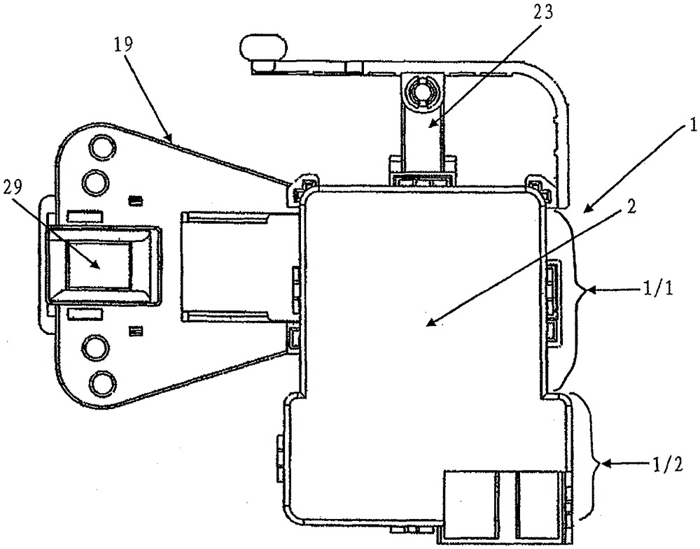
The invention discloses an electromagnetic door lock of electrical equipment. The electromagnetic door lock comprises a slider block device, a starter, a mechanical sensor and a mechanical linkage device, wherein the slider block devices is moved to a closing position along with shutoff of a door of the electrical equipment, the starter is used for providing power for switching on and switching off a switch device, the mechanical sensor is used for determining the closing position of the slider block device (20), when the slider block device is not located at the closing position, the starter is locked by the mechanical linkage device, and when the slider block device is located at the closing position, the starter is released by the mechanical linkage device, so that the switch device is located at a switch-on position. The mechanical sensor and the mechanical linkage device not only control the electromagnetic door gate in use of the electrical equipment, but lock movable components in the electromagnetic door gate in a transportation process so as to prevent the movable components from playing in the transportation process, and avoid from causing the components of the electromagnetic door lock in an abnormal state.

Description

technical field [0001] The invention relates to a door lock for commercial or household appliances, in particular to an electromagnetic door lock with a door position sensing device. Background technique [0002] The normal use of electrical equipment has certain requirements on the door lock mechanism of the equipment. When the door of commercial or household electrical equipment (such as washing machine, dishwasher, etc.) is not fully closed, the door lock mechanism should be able to prevent the door lock mechanism from malfunctioning, and avoid the change of the door lock state and affect the subsequent operation of the electrical equipment. [0003] Some existing electromagnetic door locks may cause malfunction of the electromagnetic door lock due to lack of a door position sensing device. For example, when the door of the washing machine is not closed (or not fully closed), the electromagnetic door lock is in a wrong locked state, which affects the subsequent operation...

Claims


Application Information

Patent Timeline
Patent Type & Authority Patents(China)
IPC IPC(8): E05B47/00
Inventor 黎松
Owner ILLINOIS TOOL WORKS INC
Why Eureka
Try Eureka