

Pump ring used for mechanical seal
A technology of mechanical seals and pump effect rings, which is applied in the direction of engine seals, mechanical equipment, engine components, etc., can solve problems such as poor fluid circulation, high heat on the sealing end surface, and short service life of mechanical seals, so as to reduce fluid temperature and improve pump performance. Sending capacity, increase the effect of fluid circulation
Inactive Publication Date: 2012-09-19
DALIAN HUAYANG SEALS
View PDF11 Cites 2 Cited by
- Summary
- Abstract
- Description
- Claims
- Application Information
AI Technical Summary
Problems solved by technology
[0003] In the existing technology, the pumping capacity of the pump efficiency ring is low, the fluid circulation at the sealing end face is poor, the heat generated by the friction between the sealing end faces is high, the fluid temperature at the sealing end face is high, and the service life of the mechanical seal is short
Method used
View moreImage
Smart ImageViewing Examples


Examples
Embodiment Construction
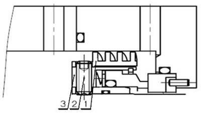
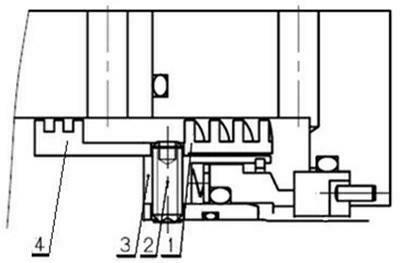
[0011] Such as figure 2 As shown, a pump effect ring for a mechanical seal includes a spiral pump effect 1, and a labyrinth seal 4 is connected to one side of the spiral pump effect 1; the spiral pump effect 1 and the labyrinth seal 4 are an integral structure; The tooth width, tooth height and the gap with the pump cover of the labyrinth seal 4 have different design dimensions according to different working condition parameters.
[0012] The present invention is installed on the drive sleeve 3 through the top wire 2 .
Login to View More PUM
 Abstract
The invention discloses a pump ring used for a mechanical seal, which comprises a screw-type pump; and a labyrinth seal is connected to one side of the screw-type pump. The pump ring has the advantages that the pumping capacity of the pump ring is improved, and the circulation of fluid on a seal end surface is accelerated, so that the effect of heat exchange and cooling of the seal end surface can be achieved, the temperature of fluid at the seal end surface is reduced, and the service life of the mechanical seal is prolonged.
Description
technical field [0001] The invention relates to the technical field of mechanical seals, in particular to a pump effect ring for mechanical seals. Background technique [0002] The pump effect ring refers to the device that is set on the outer circle of the sealing rotating part and relies on the pump effect generated when it rotates to make the sealing fluid circulate. [0003] In the prior art, the pumping capacity of the pump efficiency ring is low, the fluid circulation at the sealing end faces is poor, the heat generated by the mutual friction of the sealing end faces is high, the fluid temperature at the sealing end faces is high, and the service life of the mechanical seal is short. Contents of the invention [0004] The object of the present invention is to overcome the above disadvantages and provide a pump effect ring for mechanical seal. [0005] The technical solution adopted by the present invention to achieve the above object is: a pump effect ring for mecha...
Claims
Login to View More Application Information
Patent Timeline
 Patent Type & AuthorityApplications(China)
IPC IPC(8): F16J15/447
Inventor李雪怡陈新龙
OwnerDALIAN HUAYANG SEALS