Supercharge Your Innovation With Domain-Expert AI Agents!

Electric rotating machine

A technology for rotating electrical machines and rotor coils, applied in the direction of measuring electricity, electrical components, measuring electrical variables, etc., can solve problems such as difficult to detect ground faults

Inactive Publication Date: 2012-09-19
HITACHI LTD
View PDF8 Cites 2 Cited by
  • Summary
  • Abstract
  • Description
  • Claims
  • Application Information

AI Technical Summary

Problems solved by technology

In addition, even after the calculation of the output or current, it is necessary to measure the amount of change in the neutral point current from the healthy state, so the detection is sometimes limited to the range where no malfunction occurs
[0009] In addition, when the electric brake used in the generator motor is applied, the electromotive force of the coil is canceled by the rotor current, so the change of the neutral point current of the neutral point grounding device and its converted voltage becomes small, and it is considered difficult to detect according to these methods Ground Fault

Method used


Image

  • Electric rotating machine
  • Electric rotating machine
  • Electric rotating machine

Examples


Embodiment 1

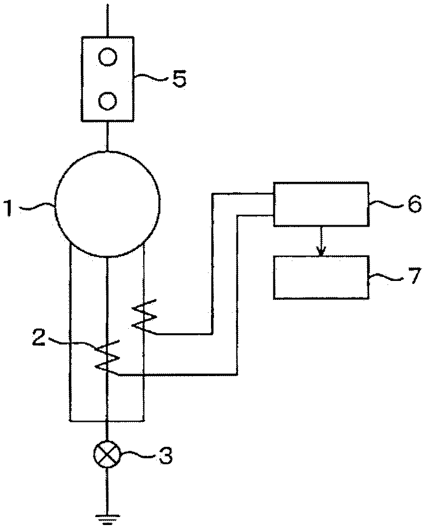
[0055] figure 1 It is a configuration diagram showing Embodiment 1 of the present invention. The neutral point side of the rotor coil of the rotating electric machine 1 is ground-faulted via the circuit breaker 3 after three phases are short-circuited. The current measurement unit 2 is arranged in two of the three phases of the rotor coil to measure the current. The measured two-phase currents are detected by the current detection device, and the calculation device 7 compares the harmonic components of the two-phase currents, and if there is a difference in the harmonic components between the two phases, it is determined that the coil ground fault.

[0056] Figure 10 The coil ground fault detection flow of Embodiment 1 is shown. Current detection 21 is performed by the current detection device 6, and periodic waveform extraction 22 and higher harmonic component calculation 24 are carried out in the calculation device 7 based on the information thereof, and the result base...

Embodiment 2

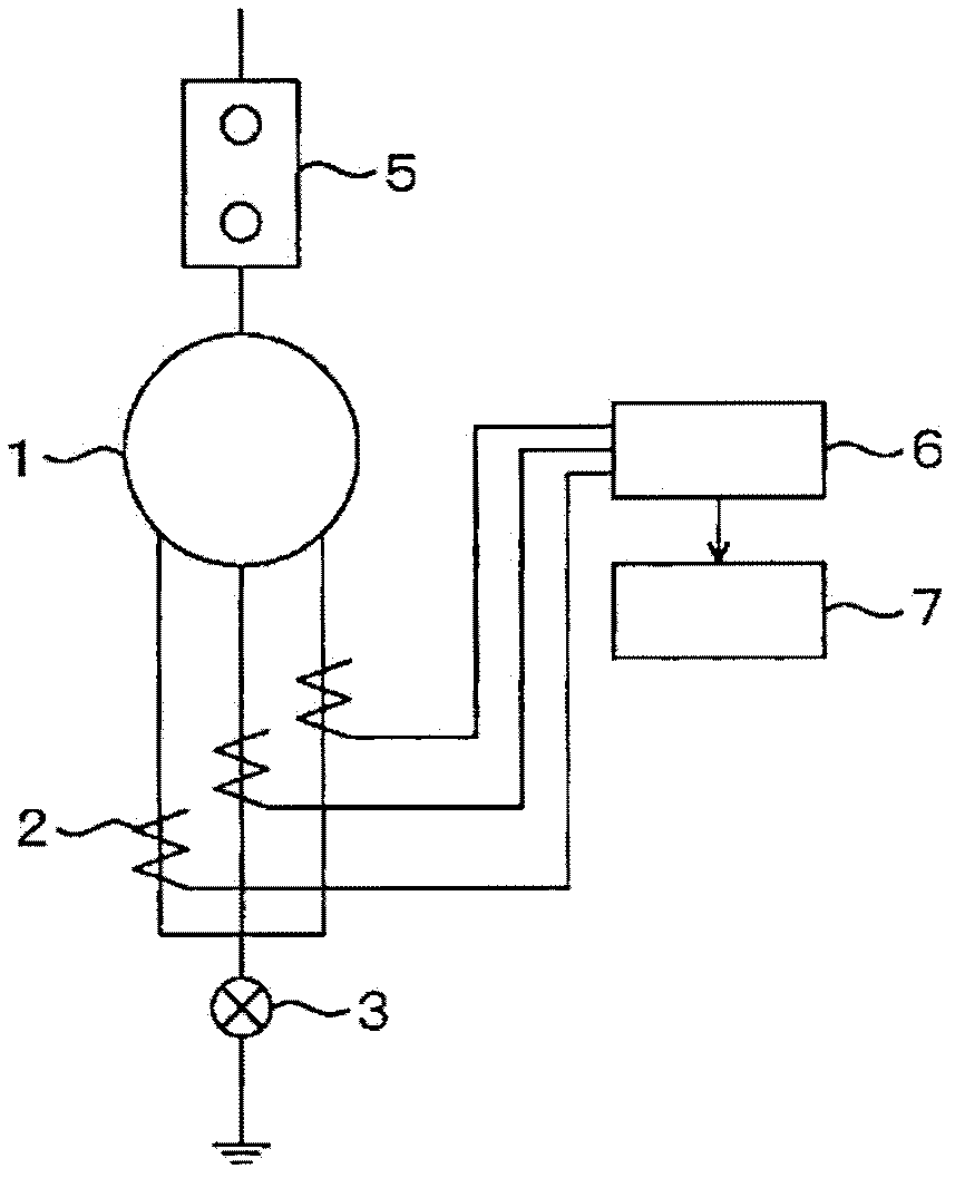
[0064] figure 2 It is a configuration diagram showing Embodiment 2 of the present invention. In Embodiment 1, an example of comparing currents of two phases was shown, but all three phases can be compared in the rotor coil which is the target of current measurement.

Embodiment 3

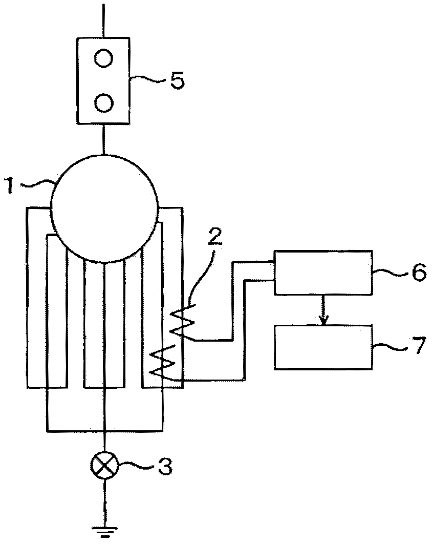
[0066] image 3 It is a configuration diagram showing Embodiment 3 of the present invention. A three-phase rotor coil composed of three parallel circuits is implemented in the rotating electric machine 1 , current measuring means 2 are provided in two parallel circuits of one phase, and current measuring means 2 are provided in one circuit of the other phase. The computing device 7 compares the harmonic components based on the currents of two parallel circuits of the same phase or the current of one circuit of another phase detected by the current detecting device 6, and when there is a difference in the harmonic components between the circuits , it is determined that there is a coil ground fault.

[0067] In a circuit in which a coil ground fault has occurred, the current waveform is different from that of other parallel circuits due to superimposition of the ground fault current. Therefore, coil ground fault detection can be performed by comparing current components betwee...


PUM


Abstract

This invention aims to provide an electric rotating machine which is free from the procedure of selecting different preset neutral current values for different types of machines, and which can detect a ground fault in a coil without suffering any erroneous operation. To solve the problem, the electric rotating machine having three phase rotor coils has a grounding resistor at a neutual point; at least two phase rotor coils are provided with current measuring apparatuses. Phase currents are compared, and when high-order harmonic components differ from each other along with the phase, it is determined that a ground fault has occurred in the coils.

Description

technical field [0001] The invention relates to a protective rotating electrical machine which detects a coil ground fault in a rotor coil. Background technique [0002] Generally, a ground fault of a rotor coil in a rotating electrical machine is determined by comparing a neutral point current at the time of a ground fault occurrence with a preset value or with a value changed from an output or the like. Figure 8 An example of a conventional rotating electric machine that detects a coil ground fault is shown. The neutral point side of the rotor coil of the rotating electric machine 1 is ground-faulted via the circuit breaker 3 and the neutral point grounding resistor 10 after the three phases are short-circuited, and the neutral point current is measured by the circuit measurement unit 2 . The measured neutral point current is detected by the current detection device 6, and then compared with a predetermined value by the arithmetic device 9, and it is judged as a coil grou...

Claims


Application Information

Patent Timeline
Patent Type & Authority Applications(China)
IPC IPC(8): G01R31/06
CPCG01R31/343H02H7/06G01R31/025G01R31/52
Inventor 中原明仁冈田雅之粥川滋广
Owner HITACHI LTD
Features
  • R&D
  • Intellectual Property
  • Life Sciences
  • Materials
  • Tech Scout
  • Unparalleled Data Quality
  • Higher Quality Content
  • 60% Fewer Hallucinations
Learn More