Supercharge Your Innovation With Domain-Expert AI Agents!

Multiphase load control method

A control method and phase load technology, applied in the control system, motor control, AC motor control and other directions to achieve the effect of improving insulation and eliminating ground faults

Inactive Publication Date: 2009-03-11
DAIKIN IND LTD
View PDF3 Cites 3 Cited by
  • Summary
  • Abstract
  • Description
  • Claims
  • Application Information

AI Technical Summary

Problems solved by technology

[0007] However, in the techniques described in the aforementioned documents, hardware for detecting ground faults is required

Method used


Image

  • Multiphase load control method
  • Multiphase load control method
  • Multiphase load control method

Examples


Embodiment Construction

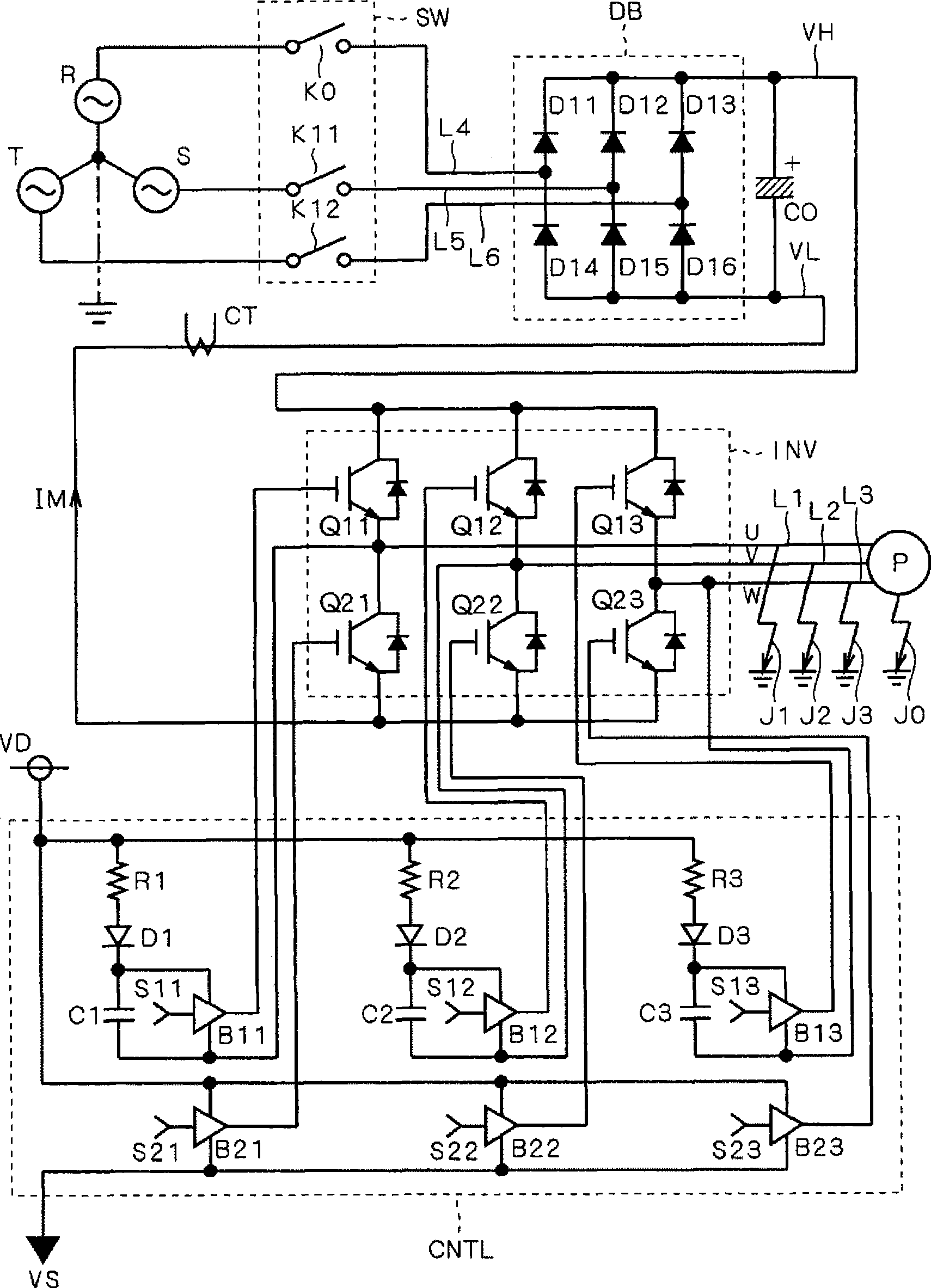
[0026] figure 1 It is a circuit diagram illustrating a multi-phase load and its driving device that can perform the control method of the multi-phase load of the present invention.

[0027] The electric motor P functions as a three-phase load, and drives, for example, a refrigerant compressor of an air conditioner (not shown). The electric motor P is insulated from the ground by, for example, insulating oil (not shown).

[0028] Output lines L1 , L2 , and L3 corresponding to U-phase, V-phase, and W-phase, respectively, are connected to the motor P, and the motor P is driven by three-phase currents flowing through these output lines.

[0029] Input lines L4 , L5 , and L6 are connected to three-phase power supplies of R-phase, S-phase, and T-phase. A switch group SW is provided for them. The switch block SW has switches K0 , K11 , K12 which are located on input lines L4 , L5 , L6 . The switch K0 can be turned on regardless of whether the switches K11, K12 are turned on or of...


PUM


Abstract

Before starting operation of an inverter (INV), only an R-phase switch (K0) of switches (SW) is turned on with an S-phase switch (K11) and a T-phase switch (K12) kept open. At least one of three low-arm switches (Q21, Q22, Q23) is turned on. If a ground fault (J0) is caused because of an insulation failure of a motor (P), current flows from an R-phase power supply through the conducting switch, a low-arm diode (D14) of the R-phase, and the R-phase switch. This current (IM) is detected by a current transformer (CT) conventionally provided to detect whether or not an overcurrent is flowing during the operation of the inverter. If no ground fault occurs, this current does not flow. That is, on the basis of the presence / absence of the current flow, it is possible to detect whether or not a ground fault occurs in the motor.

Description

technical field [0001] The invention relates to a control method of a drive device for driving multi-phase loads. Background technique [0002] A compressor used in an air conditioner or the like has a motor that drives a compression member that compresses refrigerant or the like. Moreover, this motor is insulated from the casing and the like not only by the protective film of the winding but also by insulating oil. When the compressor is not in operation for a long period, the lubricating oil will become wet, and the insulation of the compressor will deteriorate. If the deterioration is severe, it may cause a ground fault of the compressor. [0003] Techniques for detecting insulation deterioration of a compressor by detecting a current caused by such a ground fault are described in Patent Documents 1 to 3, for example. [0004] Patent Document 1: Japanese Patent Laid-Open No. 5-328739 [0005] Patent Document 2: Japanese Patent Laid-Open No. 5-328740 [0006] Patent Do...

Claims


Application Information

Patent Timeline
Patent Type & Authority Applications(China)
IPC IPC(8): H02M7/48H02P27/06
CPCH02P29/022H02P29/028H02P29/032
Inventor 八木达小仓健
Owner DAIKIN IND LTD
Features
  • R&D
  • Intellectual Property
  • Life Sciences
  • Materials
  • Tech Scout
  • Unparalleled Data Quality
  • Higher Quality Content
  • 60% Fewer Hallucinations
Learn More