Flexible modular building framework

a modular building and flexible technology, applied in the field of building frameworks, can solve the problems of inability to adapt to the welded metal beams, inconvenient high on-site construction cost and time, and achieve the effects of reducing the use of skilled manpower, reducing the number of separate components, and saving considerable cos

Inactive Publication Date: 2008-07-31
PORTER WILLIAM H
View PDF1 Cites 98 Cited by
  • Summary
  • Abstract
  • Description
  • Claims
  • Application Information

AI Technical Summary

Benefits of technology

[0006]The present invention focuses on flexible modular building structures with different junctures for use in a building frame, where the structures can be assembled by bolting beams together. Separate connectors are used to connect wood-product beams to tubular metal columns, with the connectors defining an angle of the beams to the columns. By the present invention, separate brackets do not need to be welded to the beam ends. The present invention saves considerable cost by reducing separate components, by reducing the use of skilled manpower, by reducing secondary operations, and by making for a more efficient assembly, including the ability to make adaptations at the construction site. Further, a more basic set of components can be inventoried at a common location, such as at a building supply company, thus making it more likely that necessary building supplies are available yet at a reasonable cost.

Problems solved by technology

This results in considerable on-site construction cost and time due to the need for skilled labor.
Also, it is noted that welding is a secondary operation that is expensive, time-consuming, manually-intensive, and that requires significant quality assurance to insure that quality long-lasting welds are made.
It is noted that welded metal beams are not easily adapted, but instead must be accurately made to specification, which results in every construction having custom-configured or nearly-custom-configured components.
It is not cost-effective for most building supply companies to inventory a large number of these “configured components” since such a large number of them would be required.
. . since welds and weld-adjacent beam walls can develop stress cracks and fail over time.
In traditional welded steel beam constructions (e.g., plates welded to ends of columns), it is difficult to form highly accurate joints using traditional saw cutting operations, since saw blades tend to wander and wear, making them difficult to control with high accuracy.
Other factors also affect inconsistent cutting, such as the need to repeatedly loosen and re-fixture a tubular beam for successive cuts.
All of this leads to inconsistent cut locations and higher-than-desired tolerances, which in turn leads to additional concerns about juncture stresses and integrity of junctures in an assembled / connected beam arrangement of building structures.

Method used


Image

  • Flexible modular building framework
  • Flexible modular building framework
  • Flexible modular building framework

Examples


Embodiment Construction

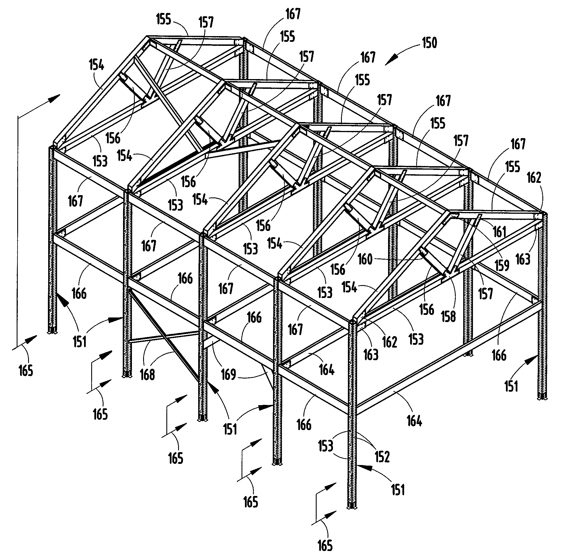
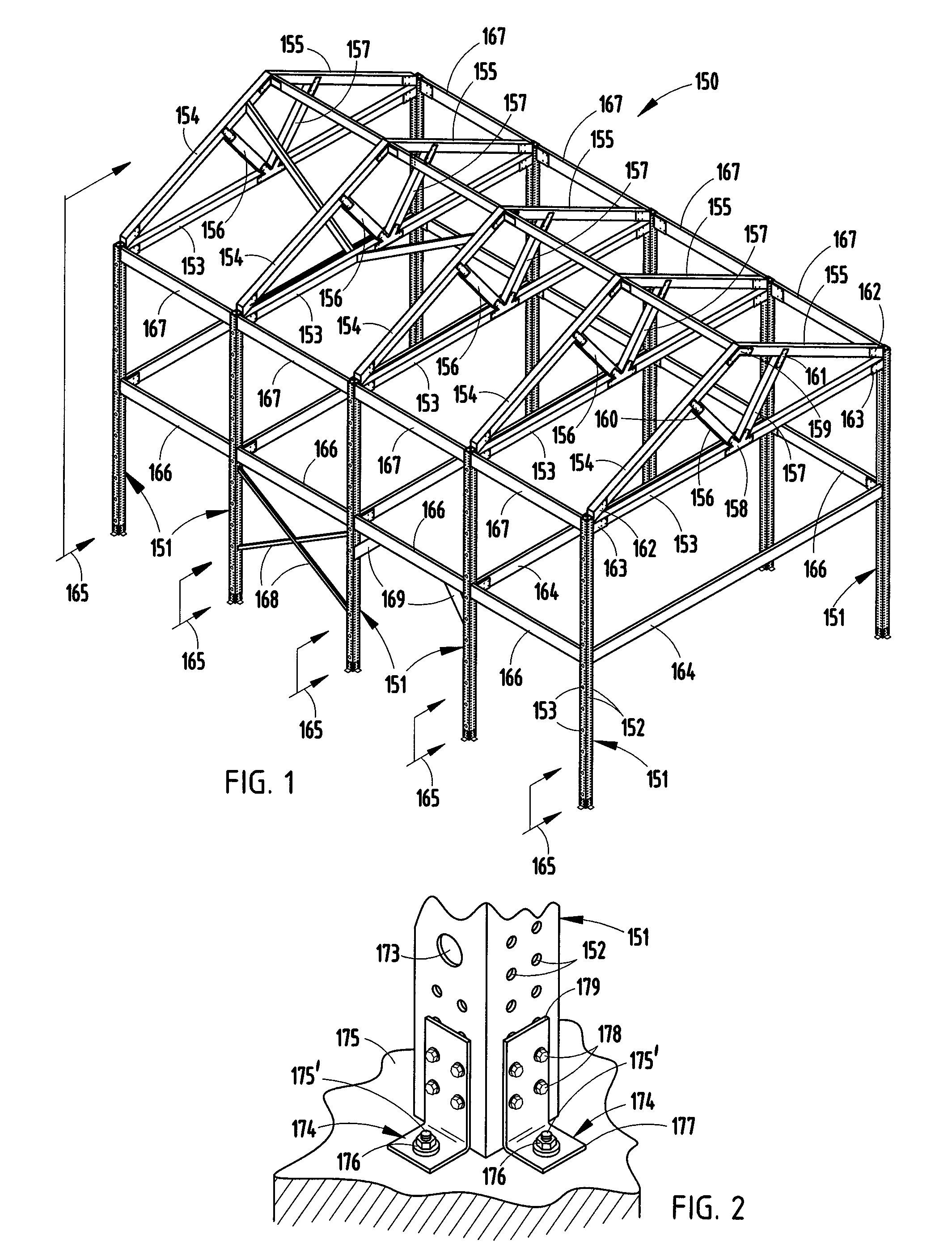
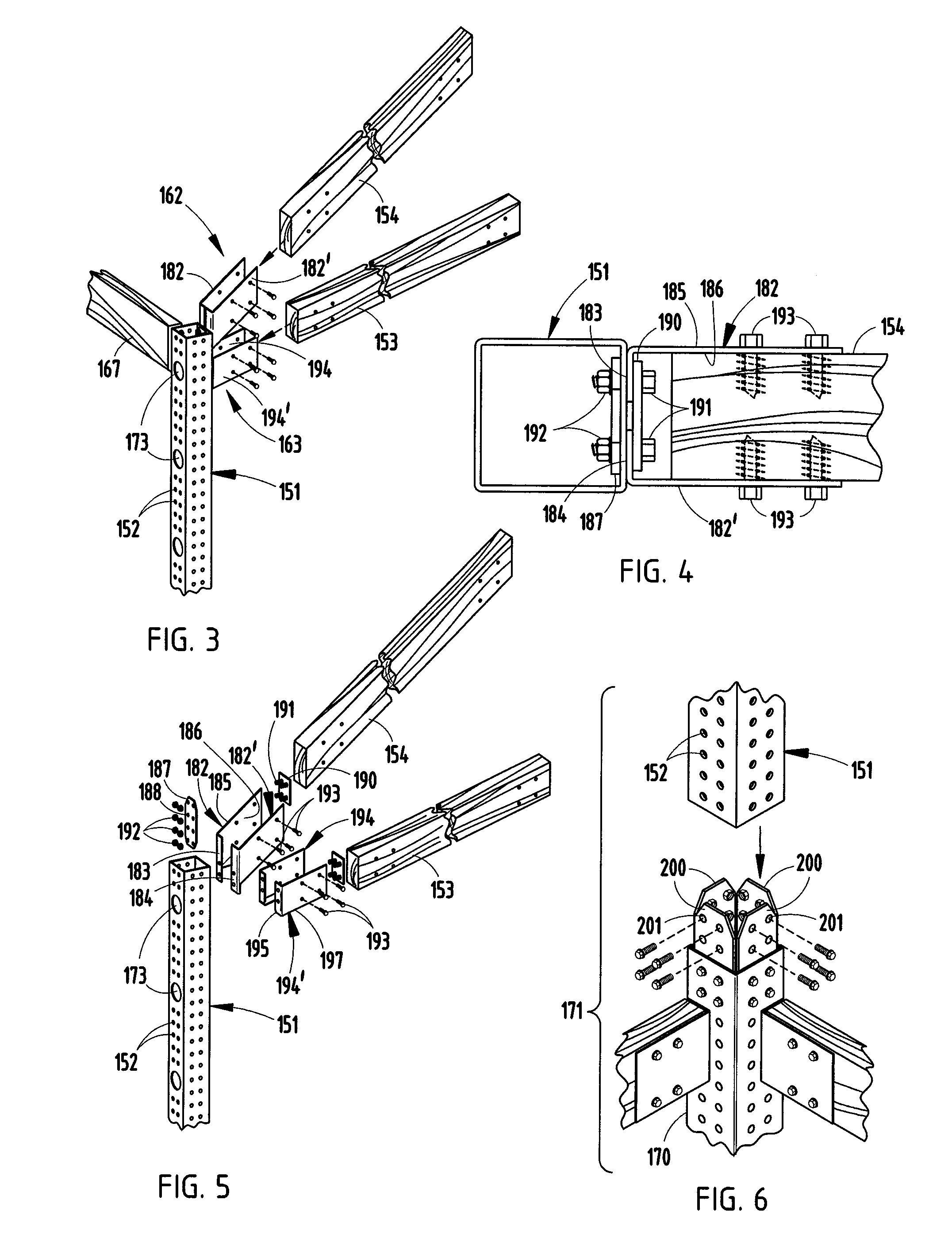
[0042]A building frame 150 (FIGS. 1-2) includes a plurality of four-sided tubular metal columns 151 with two rows of spaced-apart pre-formed holes 152 (laser cut or drilled) on each side; a plurality of wood-product beams 153-157 (such as glulam, cut timber, or other material made using a wood component) secured together with plates 158-161 to form a truss; and bracket connectors (162-163) bolted to a selected area on the columns 151 and bolted to an end of the wood-product beams 153-154 for securing the truss to a top of two columns 151. The components 151-163 that lie in a single plane form a “bent”165. One or more tubular metal beams 164 (or wood-product beams) can be connected between the columns 151, such as for forming a floor or ceiling support structure.

[0043]In the building illustrated in FIG. 1, six bents 165 are spaced apart and are connected by horizontal beams 166 and 167 (illustrated as wood-product beams, but could be steel tubes), with beams 166 forming part of a flo...


PUM


Abstract

A building framework includes metal columns (e.g., tubular or I-beam), wood-product beams, and bracket connectors for joining the beams to the columns to form a building joint of sufficient strength and durability for buildings suitable for human occupation. First mechanical fasteners (such as bolts and nuts) secure a selected connector to the column, and second mechanical fasteners (such as lag bolts) secure a selected beam to the connector. The columns include double rows of holes. A plurality of different connectors with differently angled flanges are provided, such that beams can be connected at a wide variety of different angles. Further, the system allows columns and/or beams to be cut at the construction site, or at a building supply company. Thus, basic building components can be inventoried in a manner not previously possible, yet the system supports a wide variety of different building frames for on-site customization and adaptability.

Description

[0001]This application claims benefit under 35 U.S.C. §119(e) of provisional application Ser. No. 60 / 887,461, filed Jan. 31, 2007, entitled FLEXIBLE MODULAR BUILDING FRAMEWORK, the entire contents of which are incorporated herein by reference.BACKGROUND[0002]The present invention relates to a building framework made from columns, beams, and bracket connectors, where the components are fastened together in a manner allowing flexible, low-cost, on-site adaptability when constructing a building. Further, the present invention relates to a building framework made from columns, beams, and bracket connectors, where the columns and beams are basic components that can be stocked and cut to length at a supply company or at a construction site, and where the bracket connectors can be selected to allow assembly for customized buildings suitable for human occupancy.[0003]Buildings have been made of block and wood (sometimes called “bricks and sticks”) for years. Part of the attraction of these ...

Claims


Application Information

Patent Timeline
Patent Type & Authority Applications(United States)
IPC IPC(8): E04B1/19E04G21/14
CPCE04B1/24E04B1/26E04B1/2608E04B2001/2652E04B2001/2451E04B2001/246E04B2001/2469E04B2001/2415E04B2001/2696
Inventor PORTER, WILLIAM H.
Owner PORTER WILLIAM H
Why Eureka
Try Eureka