Modular microreaction system

Inactive Publication Date: 2007-02-06
IMM INST FUR MIKROTECHNIK GMBH
View PDF5 Cites 54 Cited by
  • Summary
  • Abstract
  • Description
  • Claims
  • Application Information

AI Technical Summary

Benefits of technology

[0018]The functional base modules of the microreaction system according to the invention are designed to carry out various tasks. Furthermore, the individual base modules in the foil stacks likewise contain various functional elements, which fulfill different functions in a base module. The function of the individual subelements in a foil stack is determined by the structure of the individual foils, such as microstructuring and construction of additional functional components, for example resistance heating elements or sensors. The functions which an individual base module satisfies are achieved by means of selection and layer sequence of the various f

Problems solved by technology

One disadvantage of this known microreactor consists in the fact that only plate-like elements whose length and width correspond exactly to the recesses provided in the housing can be inserted into the housing.
Furthermore, no more or fewer stacks of plate-like elements can be inserted into such a housing than is predefined by the housing configuration.
A further disadvantage of this known microreactor consists in the fact that the plate-like elements often ex

Method used


Image

  • Modular microreaction system
  • Modular microreaction system
  • Modular microreaction system

Examples


Embodiment Construction

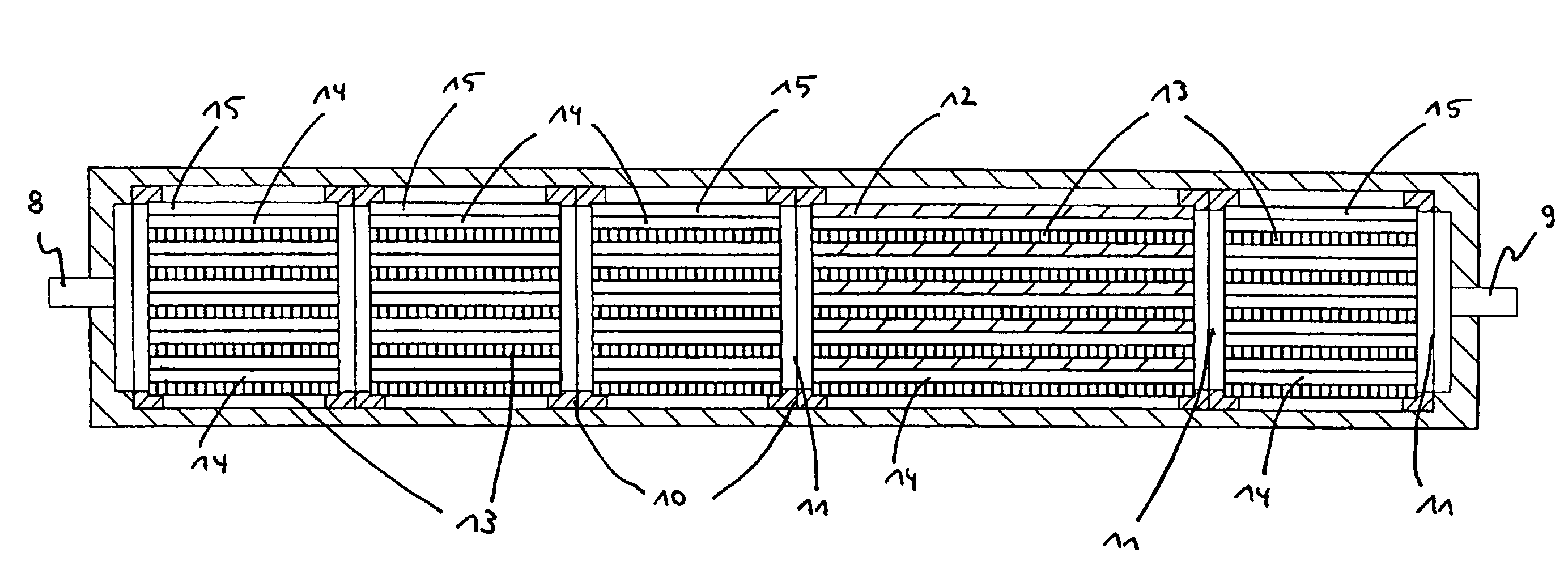
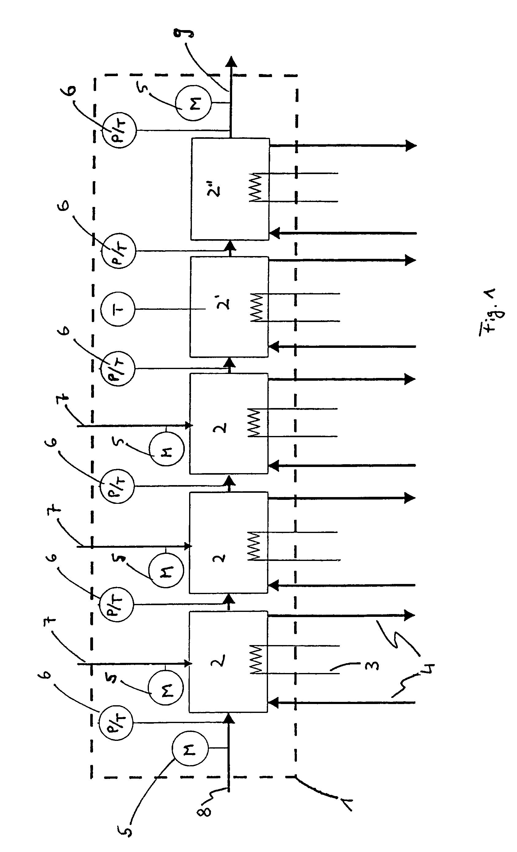
[0035]FIG. 1 reproduces the arrangement of the individual elements of a microreaction system according to the invention schematically. The housing 1, represented by a broken line, has three educt gas inlets 7, an inert gas inlet 8 and a product gas outlet 9. Arranged in the interior of the housing, one behind another, are functional base modules 2, 2′ and 2″, specifically mixer modules 2, a reaction section 2′ and a quench module (cooling or heating module) 2″. Provided at the inlets and outlets 7, 8 and 9 of the housing 1 in each case are mass flow controllers 5, which measure the gas flow and control it by driving valves. Furthermore, pressure and temperature sensors 6 are provided in front of and behind the individual base modules 2, 2′ and 2″ and are used to register and / or control these parameters. Each of the base modules 2, 2′ and 2″ illustrated is equipped with heat transfer elements, which can be supplied with cooling or heating fluid (gas or liquid) via feeds and returns 4...


PUM


Abstract

A modular microreaction system comprising a housing and functional base modules accommodated therein. The housing has at least one fluid inlet and at least one fluid outlet. The base modules are arranged one behind another in a row in the housing and being designed such that fluid can flow successively through them in series. At least some of the base modules are constructed from a plurality of substantially rectangular foils having plate-like surfaces in essentially parallel planes which foils are connected to one another and are arranged in layers one above another, forming a foil stack. At least a first of the foils having at least one of microstructured channels, sensor elements, heating elements and combinations thereof on a plate-like surface of the at least a first of the foils. Each foil stack also has at least one foil which is provided on a plate-like surface of the at least one foil with channels which are constructed such that for one fluid line they lead from one side of the foil stack to another side of the foil stack. The base modules (2, 2′, 2″) each have at least one frame element (10), which is arranged essentially perpendicular to planes of the foils, and is connected to the foil stack in a fluid-tight manner and the foil stacks, together with the frame elements, form base elements that can be inserted into and removed from the housing (1) as a unit.

Description

[0001]This application is a national stage filing under 35 U.S.C. 371 of International Application No. PCT / DE00 / 03844, filed Oct. 28, 2000 and claims priority to German Patent Application No. 199 59 249.7, filed Dec. 8, 1999.[0002]The invention relates to a modular microreaction system which is suitable for performing liquid- or gas-phase reactions, for mixing, cooling, heating of fluids or combinations thereof.[0003]The microreaction system according to the invention has a housing and functional base modules accommodated therein, the housing having at least one fluid inlet and at least one fluid outlet, and the base modules being arranged one behind another in a row in the housing and being designed such that fluid can flow successively through them. At least some of the base modules are constructed from a plurality of plate-like, substantially rectangular foils which are permanently or detachably connected to one another and are arranged in layers one above another, forming a foil...

Claims


Application Information

Patent Timeline
IPC IPC(8): B81B7/00B01J8/02B81B5/00B81B7/04B01J19/24B01F5/06B01F13/00B01J19/00
CPCB01F5/0604B01F13/0059B01F15/00935B01J19/0093B01F5/0644B01J2219/00963B01J2219/0002B01J2219/00783B01J2219/0081B01J2219/00822B01J2219/00824B01J2219/00828B01J2219/00833B01J2219/00835B01J2219/00871B01J2219/00873B01J2219/00889B01J2219/00961B01F25/422B01F25/4323B01F33/30B01F35/561
Inventor LOWE, HOLGERHAUSNER, OLIVERRICHTER, THOMAS
Owner IMM INST FUR MIKROTECHNIK GMBH
Why Eureka
Try Eureka