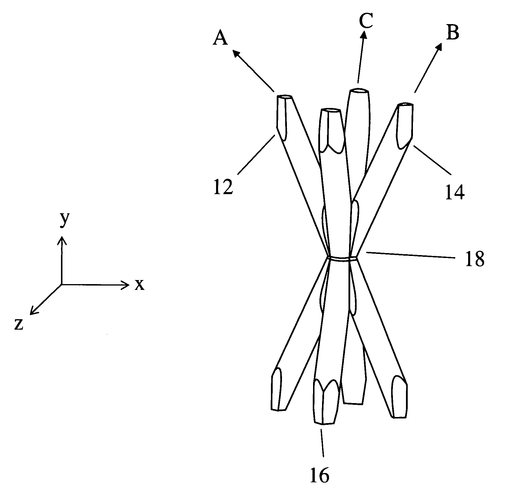
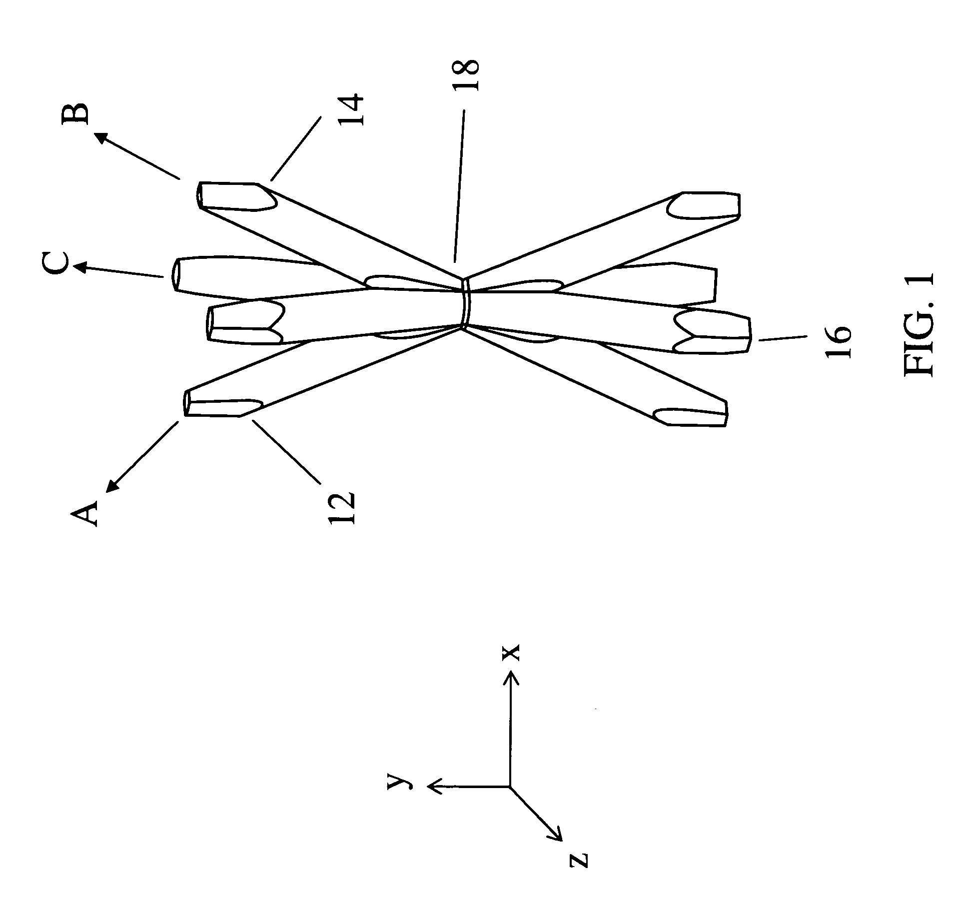
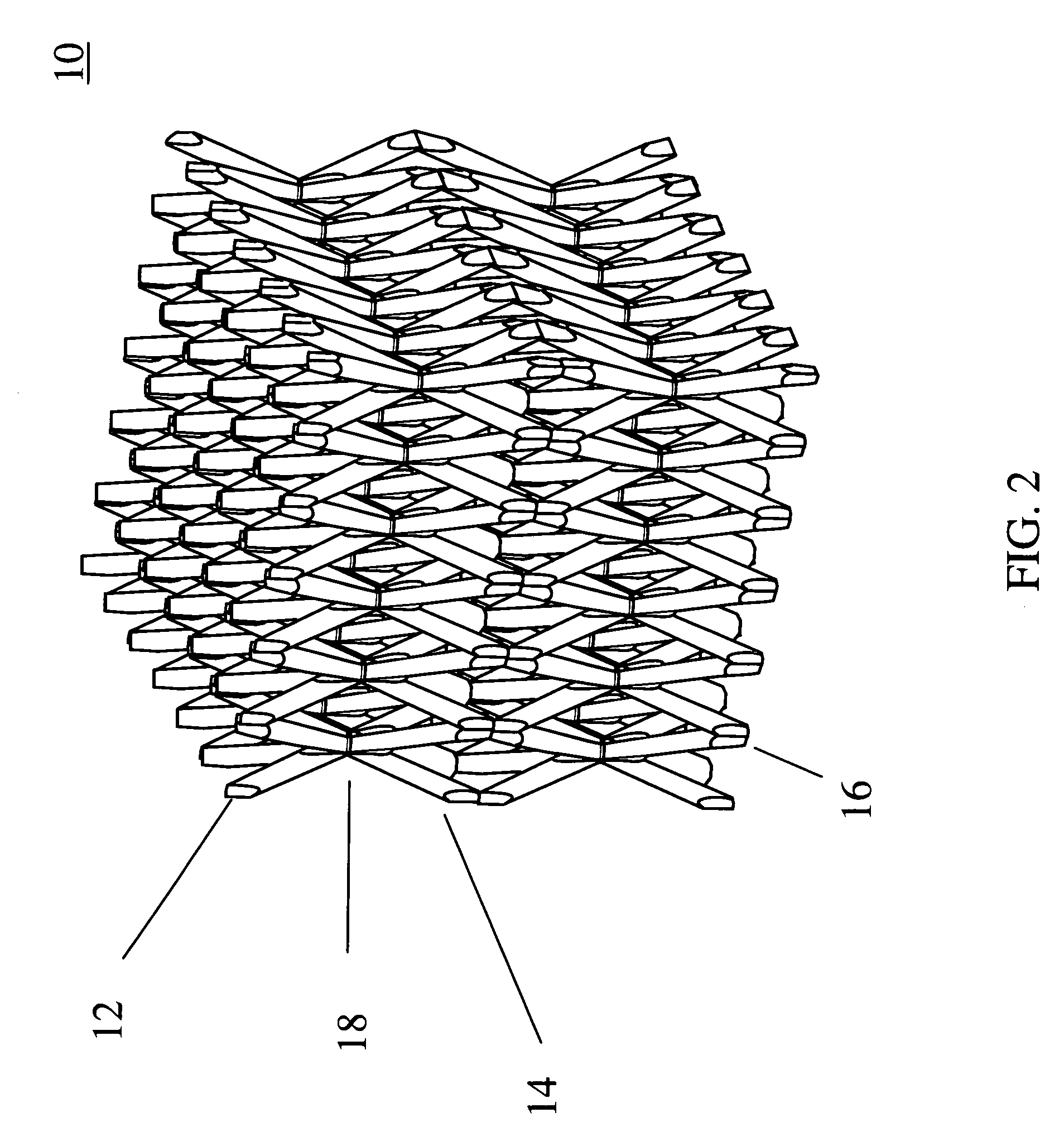
Ceramic microtruss

Inactive Publication Date: 2010-03-30
HRL LAB
View PDF10 Cites 101 Cited by
  • Summary
  • Abstract
  • Description
  • Claims
  • Application Information

AI Technical Summary

Benefits of technology

[0005]An embodiment of the present invention provides a ceramic material made of ordered ceramic rods (or trusses). These rods can be all ceramic, they may be polymer, carbon, or metal rods coated with ceramic, o

Problems solved by technology

However, ceramic foams are not ordered microstructures and suffer from the rando

Method used


Image

  • Ceramic microtruss
  • Ceramic microtruss
  • Ceramic microtruss

Examples


example 1

[0071]1. A graphite scaffold (or base structure) weighing 0.068 g is pumped into an oxygen and moisture free glove box.

[0072]2. The scaffold is placed in a 125 mL Parr Acid Digestion Bomb (autoclave) with 2 mL trichlorosilane.

[0073]3. The autoclave is sealed in the glove box.

[0074]4. The autoclave is then removed from the glove box and placed in a 250° C. oven for 12 h.

[0075]5. After 12 h, the autoclave is removed and cooled to room temperature. It is opened in a fume hood, the scaffold is removed, and washed with chloroform to remove residual trichlorosilane. Here, the scaffold is now coated with amorphous SiC.

example 2

[0076]1. A graphite scaffold weighing 0.072 g is pumped into an oxygen and moisture free glove box.

[0077]2. The scaffold and 1.9 mL trichlorosilane is placed in a 4″ long ½″ diameter steel tube. Both sides are sealed with SwageLock end caps in the glove box.

[0078]3. The tube is then removed and placed in a 500° C. oven for 6 h.

[0079]4. After 6 h, the tube is removed and cooled to room temperature. It is cut open in a fume hood and the scaffold is removed and washed with chloroform to remove residual trichlorosilane.

[0080]5. In a tube furnace under flowing N2, the sample is heated at 3° C. / min to 1500° C., held at 1500° C. for one hour, and then cooled at 5° C. / min. Here, the end product was a light gray colored Si3N4 microtruss. FIG. 8 shows the XRD pattern of the microtruss formed according to Example 2. As shown in FIG. 8, the XRD peaks index to either silicon nitride or graphitic carbon, both of which are expected in this microtruss.

Preceramic Polymers

[0081]Preceramic polymers ma...

example 3

[0082]1. A graphite scaffold is dried in an oven at 100° C.

[0083]2. A 1:1 vol:vol solution of RD-633 by Starfire Systems and OS-20 by Dow Corning was made.

[0084]3. The graphite scaffold is soaked in the RD-633 solution. It is removed and then placed in a N2 purged tube furnace.

[0085]4. The furnace is heated at 1° C. / min to 850° C., and then held at 850° C. for 1 h. The furnace is then cooled at 5° C. / min.

[0086]5. Steps 3 & 4 are repeated two times. That is, to fill the scaffold with ceramic, it is impregnated and heated for multiple cycles.


PUM

PropertyMeasurementUnit
Lengthaaaaaaaaaa
Lengthaaaaaaaaaa
Structureaaaaaaaaaa

Abstract

An ordered ceramic microstructure and a method of making the same. In one embodiment, the ceramic microstructure includes a base structure and one or more ceramic layers. The base structure includes a plurality of first truss elements defined by a plurality of first self-propagating polymer waveguides and extending along a first direction, a plurality of second truss elements defined by a plurality of second self-propagating polymer waveguides and extending along a second direction, and a plurality of third truss elements defined by a plurality of third self-propagating polymer waveguides and extending along a third direction. Here, the first, second, and third truss elements interpenetrate each other at a plurality of nodes to form a continuous material, and the base structure is self-supporting. In addition, the ceramic layers coat a surface of at least one truss element of the first truss elements, the second truss elements, or the third truss elements.

Description

FIELD OF THE INVENTION[0001]The present invention relates to an ordered ceramic microstructure (or microtruss structure) and a method of making the same.BACKGROUND OF THE INVENTION[0002]Ceramic foams can have the form of a polymer foam while being made of a sintered ceramic. They are stable at high temperatures and have attractive strength to weight ratios. However, ceramic foams are not ordered microstructures and suffer from the random interconnections in their form, thereby reducing the strength of the materials. If a material could be formed on an ordered microstructure instead of a disordered microstructure, a stronger material with possibly lower mass could be formed.[0003]As such, there is a need for a ceramic material having an ordered microstructure.SUMMARY OF THE INVENTION[0004]Aspects of embodiments of the present invention are directed towards an ordered ceramic microstructure (or microtruss structure) and a method of making the same.[0005]An embodiment of the present in...

Claims


Application Information

Patent Timeline
IPC IPC(8): B32B3/12B22F1/06
CPCB22F1/0007C04B38/0032B22F3/002C04B35/565C04B35/58Y10T428/29B22F2998/00B22F2999/00Y10T428/24149B22F1/02B22F1/004B22F1/06B22F1/062
Inventor GROSS, ADAM F.JACOBSEN, ALAN J.CUMBERLAND, ROBERT
Owner HRL LAB
Why Eureka
Try Eureka