Catalytic converter, holding material for catalytic converter and production method thereof

a catalytic converter and holding material technology, applied in the direction of machines/engines, transportation and packaging, separation processes, etc., can solve the problems of reducing the time taken until regeneration treatment, harming the human body and the environment, and affecting the performance of heat insulation performance, so as to improve the purification performance of exhaust gas

Active Publication Date: 2009-01-22
NICHIAS CORP
View PDF4 Cites 107 Cited by
  • Summary
  • Abstract
  • Description
  • Claims
  • Application Information

AI Technical Summary

Benefits of technology

[0023]The holding material for a catalytic converter of the invention is greatly enhanced in heat insulation performance by existence of the low thermal conductivity layer, and can be more improved in exhaust gas purifying performance due to the catalytic converter.

Problems solved by technology

It has recently become a problem that particulates contained in exhaust gas discharged from internal combustion engines of vehicles such as buses and trucks, construction machines and the like cause harm to the human body and the environment.
As a result, there is concern that the time taken until the regeneration treatment is required decreases.
Furthermore, the temperature difference between the internal temperature (about 600° C.) and the external temperature is large, so that when heat insulation performance of the holding material 13 is not sufficient, thermal stress is generated due to the temperature difference which occurs between a vicinity of a center portion of the catalyst carrier 12 and a vicinity of the outer peripheral portion thereof, resulting in easy occurrence of cracks in the catalyst carrier 12.
As a result, there is also concern that durability is impaired.
It becomes therefore more difficult to maintain the catalyst carrier 12 at the treatment temperature even in a region where is not a cold region.

Method used


Image

  • Catalytic converter, holding material for catalytic converter and production method thereof
  • Catalytic converter, holding material for catalytic converter and production method thereof
  • Catalytic converter, holding material for catalytic converter and production method thereof

Examples


example 1

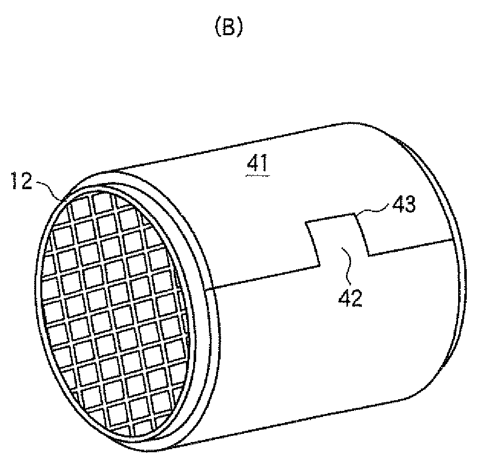
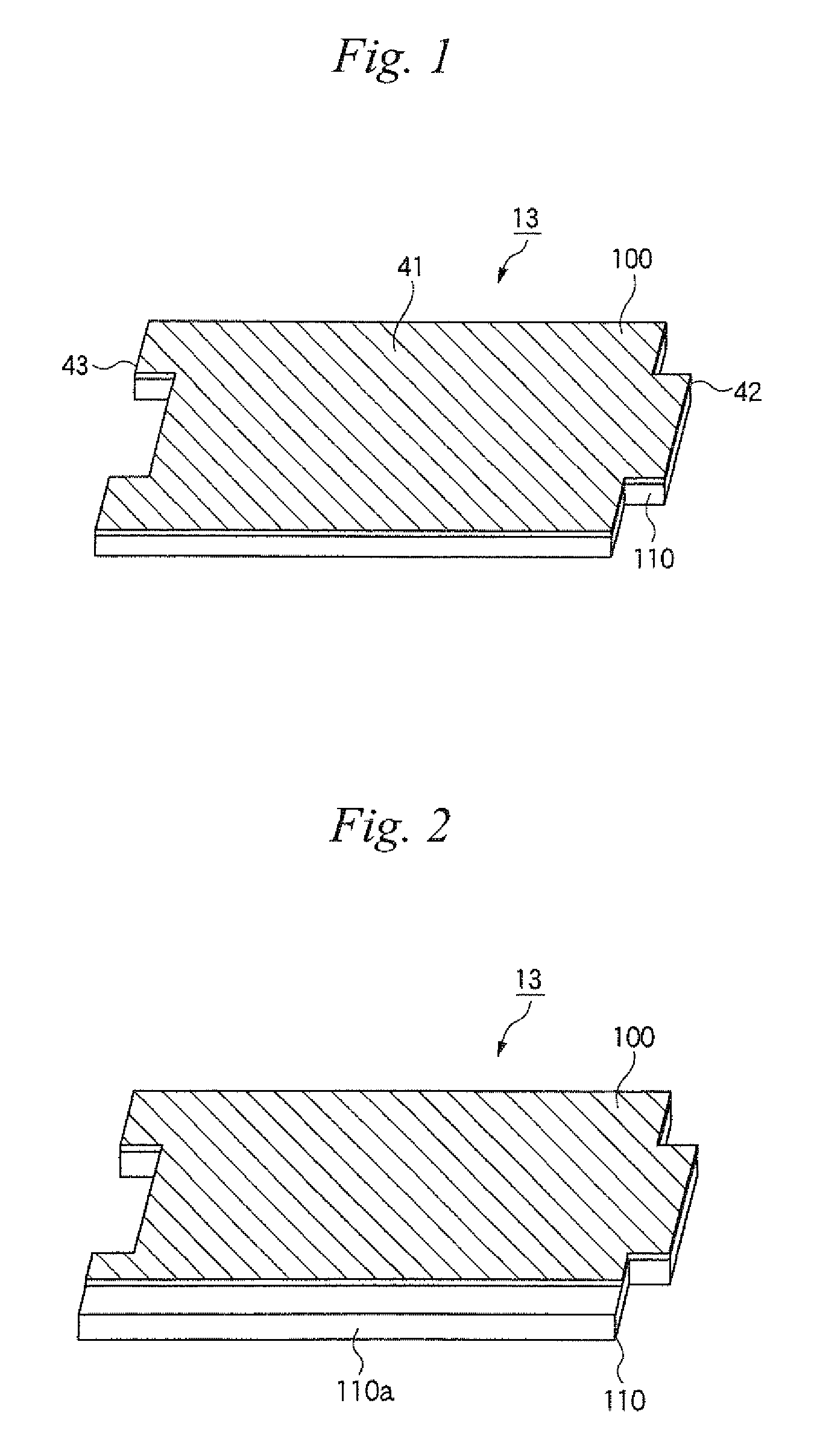
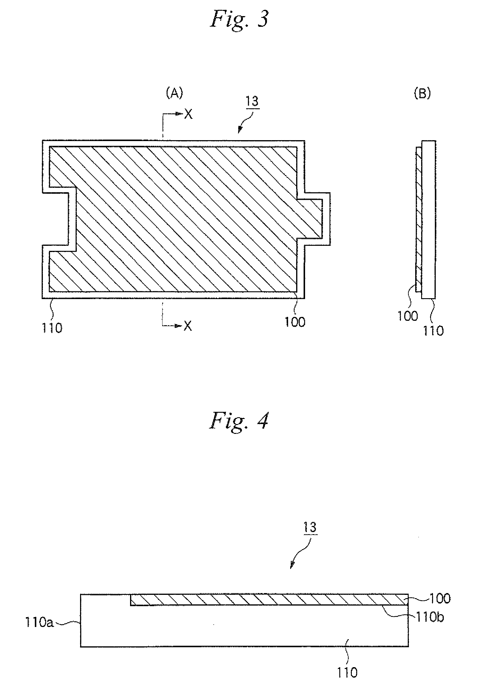
[0097]A slurry containing 10 parts by mass of an acrylic resin as an organic binder and 10,000 parts by mass of water, based on 100 parts by mass of alumina fibers (alumina: 80% by mass, silica: 20% by mass) was obtained. This slurry was poured into a tabular mold, followed by dehydration molding to obtain a wet mat. This wet mat was dried at 100° C. while compressing it using a press plate to obtain a compressed mat having a basis weight of 1,100 g / m2 and an organic content of 10%. The bulk density of the compressed mat was 0.17 g / cm3, and the thickness was 8.5 mm. A fumed silica powder having an average primary particle size of about 7 nm was kneaded in a silica cloth having a weight of 500 g / cm2, followed by compression to prepare a sheet acting as a low thermal conductivity layer. Here, the thermal conductivity at 300° C. of the sheet was 0.03 W / m·K, the thermal conductivity at 600° C. was 0.04 W / m·K, the bulk density was 0.84 g / m3, and the thickness was 0.6 mm. Then, the mat an...

example 2

[0099]A holding material shown in FIG. 1 was obtained in the same manner as in Example 1 with the exception that “Pyrogel-6650” manufactured by Aspen Aerogels, Inc. was used as the low thermal conductivity layer. Here, the thermal conductivity at 300° C. of the low thermal conductivity layer was 0.02 W / m·K, the thermal conductivity at 600° C. was 0.03 W / m·K, the bulk density was 0.12 g / cm3, and the thickness was 1 mm. The thickness of the resulting holding material was 9.5 mm.

[0100]Then, a catalytic converter was prepared by using this holding material in the same manner as in Example 1, and attached to a heating vibration tester to perform similar temperature measurement as in Example 1. As a result, it was confirmed that the temperature reached 350° C. or more after 2.5 minutes. Further, no problem occurred such as dropping off of the catalyst carrier.

example 3

[0101]A mat comprising a blanket obtained by collecting alumina fibers (alumina: 80% by mass, silica: 20% by mass) in tabular form and needling the collected fibers was prepared. Here, the bulk density of the mat was 0.15 g / cm3, and the thickness was 4.0 mm. Further, 80% by mass of a fumed silica powder having an average primary particle size of about 7 nm, 18% by mass of a silicon carbide having an average particle size of 3 μm as a radiant material, and 2% by mass of glass fibers having an average fiber diameter of 10 μm and an average fiber length of 5 mm as reinforcing fibers were mixed by a rotary mixing apparatus. Then, the resulting mixture was compression molded by a dry system to prepare a fumed silica-containing sheet used as a low thermal conductivity layer. Here, the thermal conductivity at 300° C. of the sheet was 0.025 W / m·K, the thermal conductivity at 600° C. was 0.03 W / m·K, the bulk density was 0.20 g / cm3, and the thickness was 1.5 mm. Then, the sheet was held betwe...


PUM

PropertyMeasurementUnit
thermal conductivityaaaaaaaaaa
temperatureaaaaaaaaaa
thermal conductivityaaaaaaaaaa

Abstract

The present invention relates to a holding material for a catalytic converter including a catalyst carrier, a metal casing for receiving the catalyst carrier, and the holding material wound around the catalyst carrier and interposed in a gap between the catalyst carrier and the metal casing, the holding material including a low thermal conductivity layer, in which the low thermal conductivity layer includes: a molded material containing an inorganic powder; or a composite material of a porous substrate with an aerogel.

Description

FIELD OF THE INVENTION[0001]The present invention relates to a catalytic converter (also referred to as an exhaust gas purifying apparatus) for removing particulates, carbon monoxide, hydrocarbons, nitrogen oxides and the like contained in exhaust gas discharged from an internal combustion engine such as a gasoline engine or a diesel engine, a holding material for a catalytic converter for holding a catalyst carrier in a metal casing, and a production method thereof.BACKGROUND OF THE INVENTION[0002]It has recently become a problem that particulates contained in exhaust gas discharged from internal combustion engines of vehicles such as buses and trucks, construction machines and the like cause harm to the human body and the environment. Various catalyst converters which can collect the particulates in the exhaust gas to purify the exhaust gas have been proposed.[0003]FIG. 10 is a cross-sectional view schematically showing an embodiment of a catalytic converter. In this catalytic con...

Claims


Application Information

Patent Timeline
Patent Type & Authority Applications(United States)
IPC IPC(8): B01D53/86B32B5/18B05D3/00B32B38/08
CPCF01N3/2864F01N3/2853Y10T428/249957F01N3/2842F01N3/2839
Inventor TOMOSUE, NOBUYAISOMURA, KAZUTOSHISAKANE, TADASHI
Owner NICHIAS CORP
Why Eureka
Try Eureka