Vessel sealing instrument with reduced thermal spread and method of manufacture therefor

a sealing instrument and thermal spread technology, applied in manufacturing tools, surgical forceps, other domestic articles, etc., can solve the problems of reducing the integrity of the seal, increasing the cutting edge, and difficult to maintain the tolerances necessary to form the jaw member with the desired minimal thermal spread and minimal edge, so as to facilitate the mounting of the seal plate/insulator, minimize thermal spread and collateral damage, and enhance the effect of adhesion

Active Publication Date: 2014-11-18
COVIDIEN LP
View PDF196 Cites 107 Cited by
  • Summary
  • Abstract
  • Description
  • Claims
  • Application Information

AI Technical Summary

Benefits of technology

[0011]In an embodiment, a reverse surface of the seal plate includes a plurality of ribs and / or valleys defined thereupon. An insulating layer having an obverse side and a reverse side is intimately and conformally fixed to the seal plate mounting surface such that the valleys and / or ribs of the seal plate reverse surface engage corresponding features of the insulator obverse face. An edge of the seal plate defined by the sealing surface and the side wall is radiused. The ribbed pattern of the seal plate and insulator, and the radiused edge of the seal plate provides optimal current paths while minimizing thermal spread and collateral damage, e.g., edge cutting. In some embodiments a base plate is fixed to a reverse face of the insulator to facilitate mounting of the seal plate / insulator to a jaw housing. A reverse face of the base plate may include notched, grooved, or dovetailed features adapted to enhance adhesion between the base plate and the jaw housing.
[0012]By the disclosed arrangement, sealing current is uniformly concentrated within the sealing surface of the jaws (e.g., the seal plate) while concurrently providing enhanced electrical and thermal isolation along the side walls of the seal plate. The disclosed arrangement of the electrode insulating material and the electrically conductive sealing surface provides a more consistent, high quality seal and effectively reduces thermal spread to adjacent tissue during use. Preferably, the geometry of the insulating substrate and seal plate also isolates the two electrically opposing electrodes formed by opposing seal plates within a pair of jaws from one another, thereby reducing the possibility that tissue or tissue fluids can create an unintended bridge or path for current travel.

Problems solved by technology

Excessive thermal energy should not be allowed to spread to adjacent areas of tissue, as this may diminish the integrity of a resulting seal since the energy required to form the seal is dissipated into the surrounding tissue rather than into the region intended to be sealed.
It has been found that reducing the height of the seal plate side walls may minimize thermal spread, yet, too much of a reduction in sidewall height may result in excessive current concentrations resulting in increased edge cutting.
Using prior art overmolding techniques, it is difficult to maintain the tolerances necessary to form a jaw member having the desired minimal thermal spread and minimal edge cutting properties since variations in edge height were unavoidable.
During product development cycles, where numerous and different prototypes may be built, the overmolding process may not be cost-effective and may yield unsatisfactory results, particularly when a prototype jaw member needs to be fabricated precisely for evaluation purposes.
Preferably, the geometry of the insulating substrate and seal plate also isolates the two electrically opposing electrodes formed by opposing seal plates within a pair of jaws from one another, thereby reducing the possibility that tissue or tissue fluids can create an unintended bridge or path for current travel.

Method used


Image

  • Vessel sealing instrument with reduced thermal spread and method of manufacture therefor
  • Vessel sealing instrument with reduced thermal spread and method of manufacture therefor
  • Vessel sealing instrument with reduced thermal spread and method of manufacture therefor

Examples


Embodiment Construction

[0069]Particular embodiments of the present disclosure are described hereinbelow with reference to the accompanying drawings; however, the disclosed embodiments are merely examples of the disclosure, which may be embodied in various forms. Well-known functions or constructions are not described in detail to avoid obscuring the present disclosure in unnecessary detail. Therefore, specific structural and functional details disclosed herein are not to be interpreted as limiting, but merely as a basis for the claims and as a representative basis for teaching one skilled in the art to variously employ the present disclosure in virtually any appropriately detailed structure.

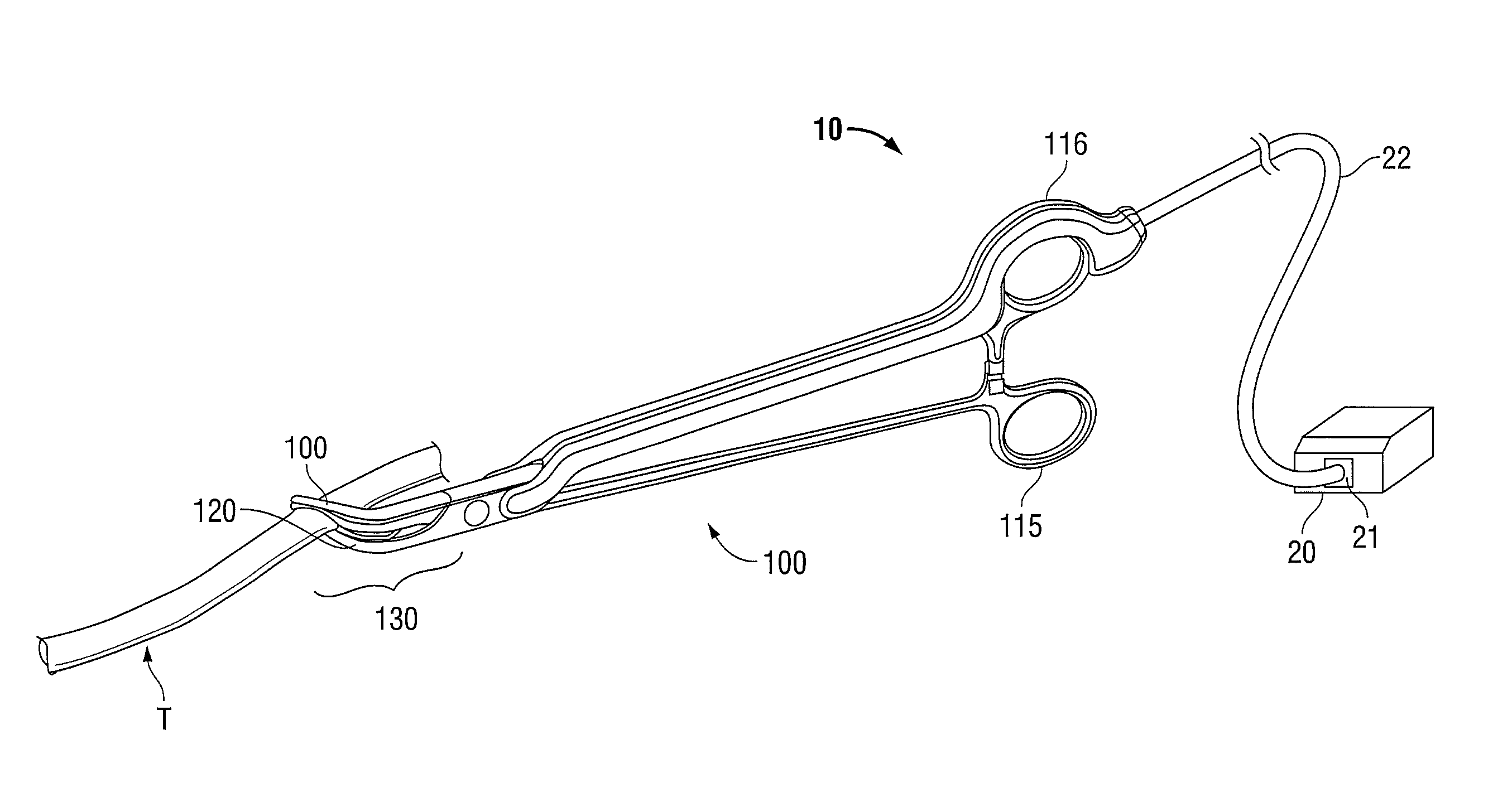
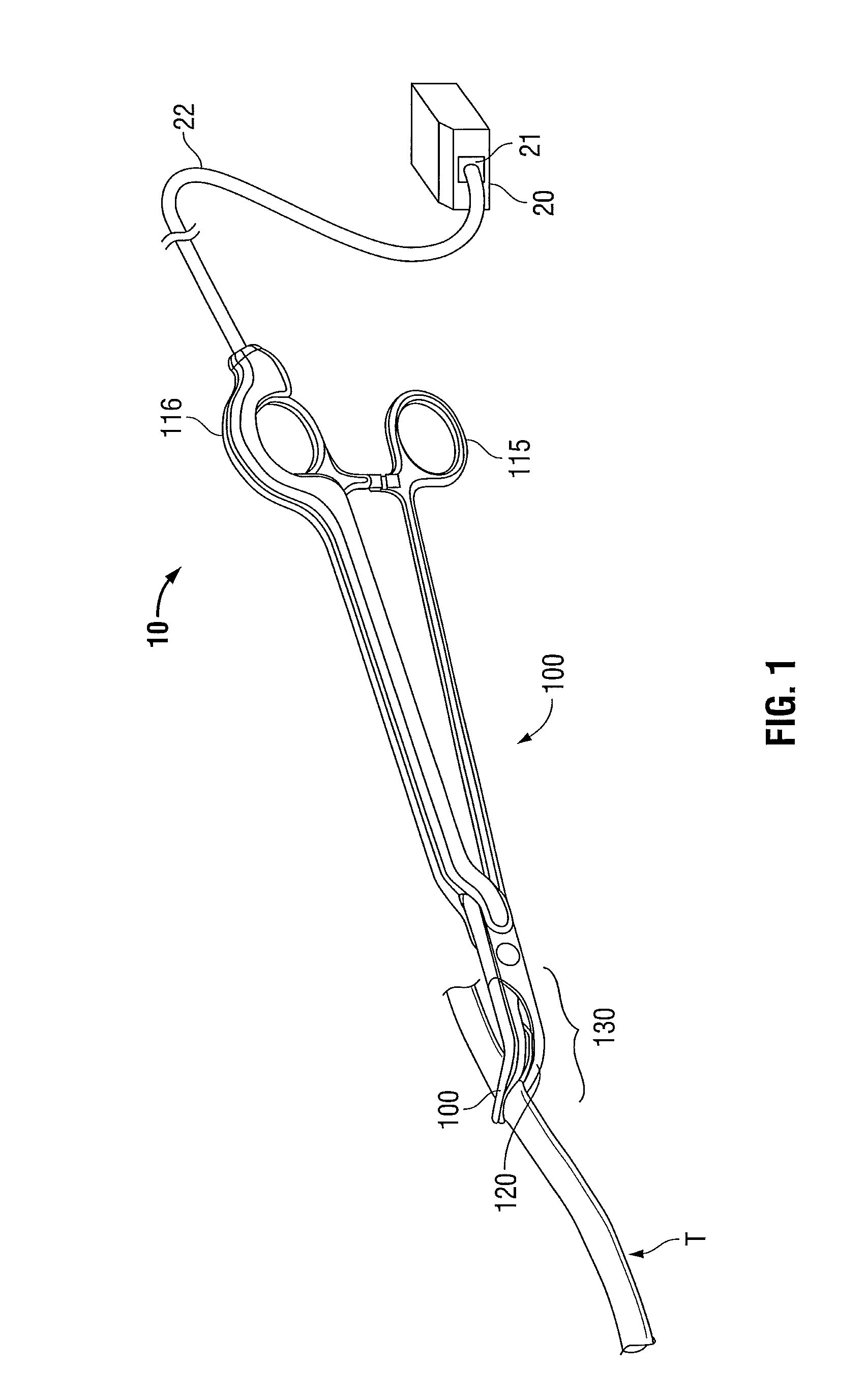
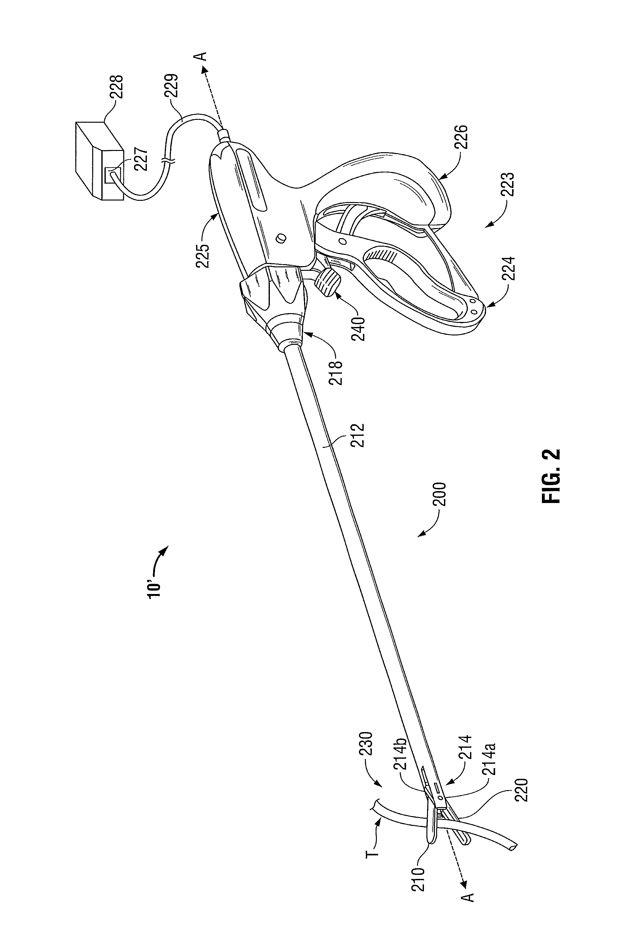
[0070]In the drawings and in the descriptions that follow, the term “proximal,” as is traditional, shall refer to the end of the instrument that is closer to the user, while the term “distal” shall refer to the end that is farther from the user. The term “obverse” shall refer to a direction facing towards a tissue cont...


PUM

PropertyMeasurementUnit
angleaaaaaaaaaa
energyaaaaaaaaaa
insulatingaaaaaaaaaa

Abstract

An electrosurgical vessel sealing instrument having a first and a second opposing jaw member at a distal end thereof, wherein each jaw member includes a jaw housing, a seal plate having a tissue contacting surface and a side wall, and an insulating region disposed on the side wall of the seal plate. The instrument includes the ability to move the jaw members relative to one another from a first position wherein the jaw members are disposed in spaced relation relative to one another to a second position wherein the jaw members cooperate to grasp tissue. The insulating region enables precision overmolding of the jaw housing to the seal plate, while advantageously reducing thermal spread and edge cutting during vessel sealing procedures.

Description

BACKGROUND[0001]1. Technical Field[0002]The present disclosure relates to electrosurgical instruments and methods for performing surgical procedures and, more particularly, to an electrosurgical vessel sealing instrument with a jaw assembly having one or more insulating members associated with the sealing plate that provide reduced thermal spread and reduced edge cutting while enabling improved dimensional tolerances during the prototyping and manufacturing process.[0003]2. Background of Related Art[0004]A hemostat or forceps is a simple pliers-like tool that uses mechanical action between its jaws to constrict tissue and is commonly used in open surgical procedures to grasp, dissect and / or clamp tissue. Electrosurgical forceps utilize both mechanical clamping action and electrical energy to effect hemostasis by heating the tissue and blood vessels to coagulate, cauterize and / or seal vascular tissue.[0005]Using electrosurgical forceps, a surgeon can elect to seal, cauterize, coagula...

Claims


Application Information

Patent Timeline
Patent Type & Authority Patents(United States)
IPC IPC(8): B23P15/00
CPCA61B18/1445A61B2017/00526A61B2018/0063A61B2018/00345A61B2018/00083A61B18/1442A61B2018/00404Y10T29/49986B29C49/071B29C2949/0715B29B11/14B29C70/78B29C70/88B29K2077/00B29L2031/7546
Inventor BRANDT, KIM V.AQUINO, ALLAN G.
Owner COVIDIEN LP
Why Eureka
Try Eureka