
Device for fixing clutch slave cylinder

A clutch cylinder and fixing device technology, applied in the field of machinery, can solve the problems of increasing production costs, waste of resources, etc., and achieve the effects of enhancing applicability, reducing weight, and increasing the range of installation

Active Publication Date: 2012-09-26
HANGZHOU BRANCH ZHEJIANG GEELY AUTOMOBILE RES INST +2
View PDF9 Cites 1 Cited by
  • Summary
  • Abstract
  • Description
  • Claims
  • Application Information

AI Technical Summary

Problems solved by technology

Re-developing a new sub-pump body due to minor installation differences not only wastes resources but also increases production costs

Method used


Image

  • Device for fixing clutch slave cylinder
  • Device for fixing clutch slave cylinder
  • Device for fixing clutch slave cylinder

Examples


Embodiment 1

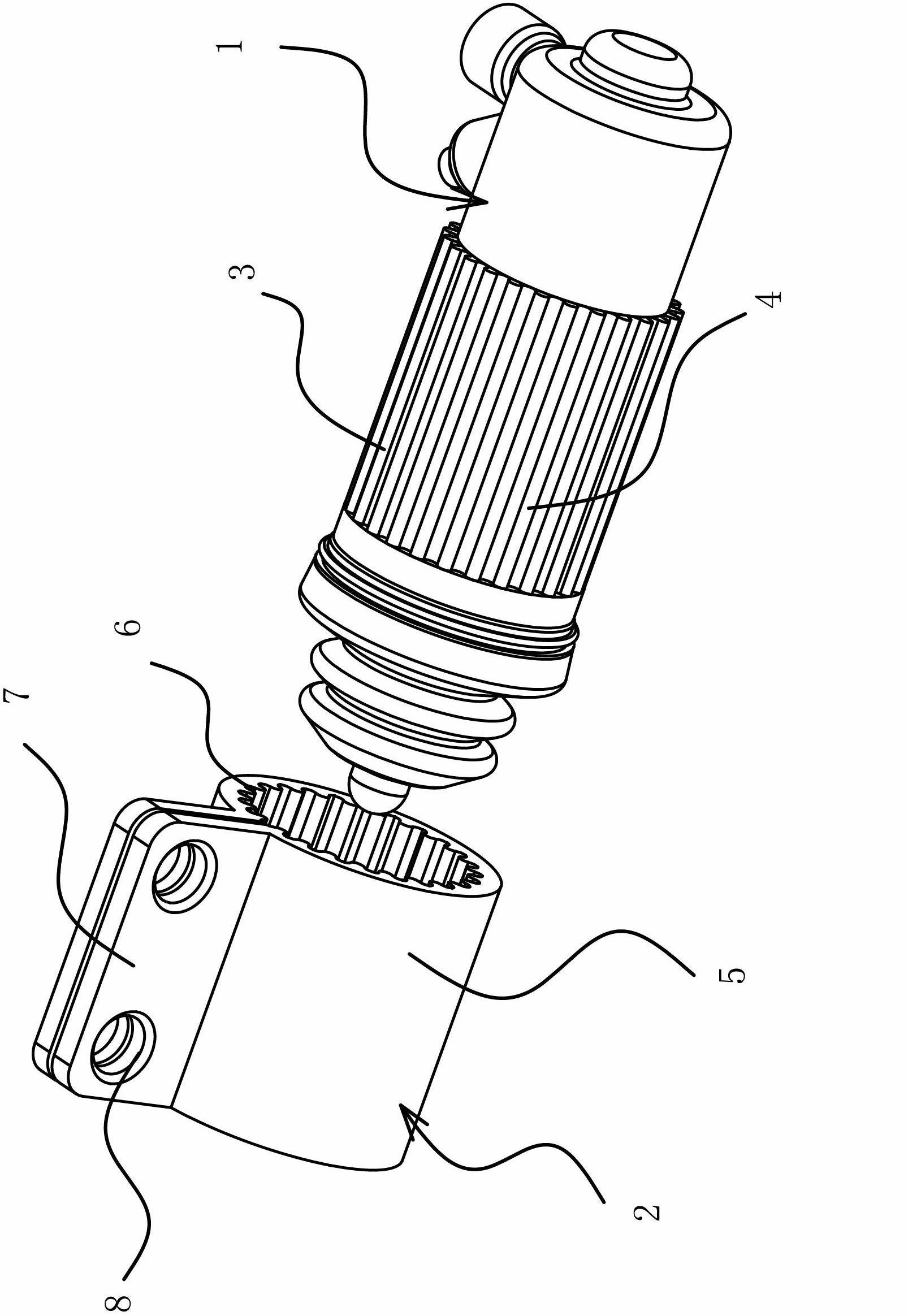
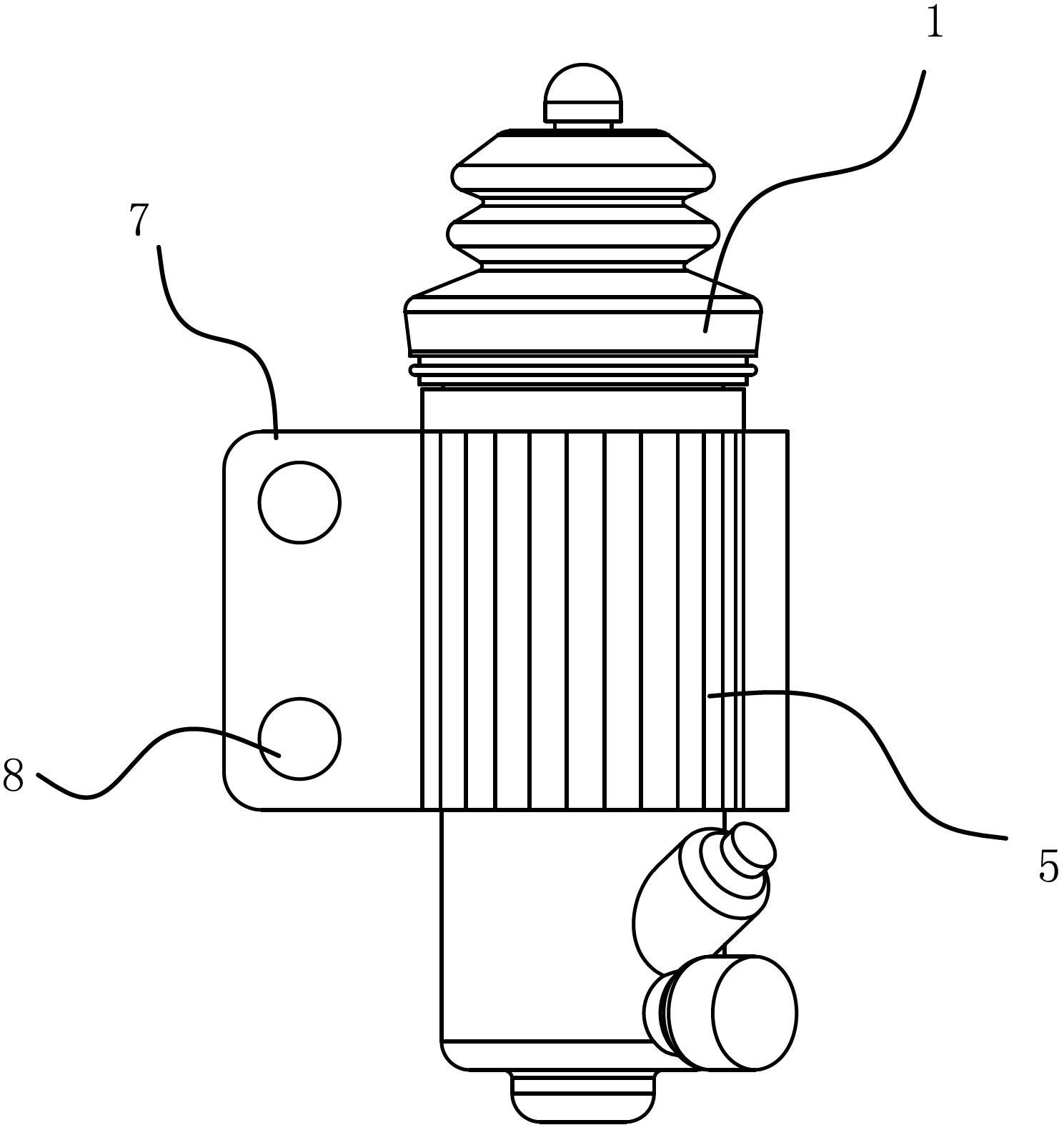
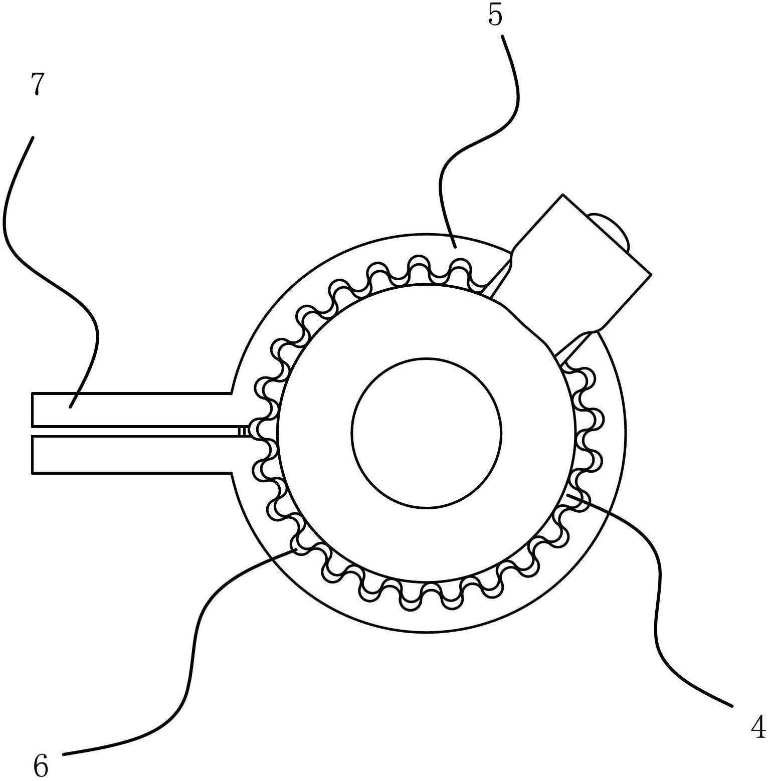
[0027] Such as figure 1 , figure 2 , image 3 As shown, the clutch slave cylinder can be connected to the transmission housing through the fixing device, and the clutch slave cylinder has a pump body 1 . The fixing device of the clutch slave cylinder includes a cylindrical connection part 3 on the clutch slave cylinder pump body 1 and a mounting flange 2 for fixing the pump body 1 on the transmission case. The mounting flange 2 has a positioning cylinder 5 nested with the connecting portion 3 of the pump body 1 , and a positioning mechanism capable of fixing the pump body 1 both circumferentially and axially is provided between the positioning cylinder 5 and the connecting portion 3 .

[0028] Specifically, the positioning mechanism includes a number of racks 4 circumferentially distributed on the connecting portion 3 and a number of tooth grooves 6 distributed on the inner surface of the positioning cylinder 5 and corresponding to the number of the racks 4 . When the conne...

Embodiment 2

[0032] Embodiment 2 is basically similar in structure to Embodiment 1, the difference lies in the positioning mechanism. Such as Figure 4 , Figure 5 As shown, the positioning mechanism of Embodiment 2 includes positioning pins 9, several through holes 10 provided in the circumferential direction of the positioning cylinder 5, and positioning grooves 11 provided on the connecting portion 3 of the pump body 1. When the positioning cylinder 5 is sleeved on the connecting portion 3, rotate the connecting part 3 to align the corresponding positioning groove 11 with the through hole 10 and fix the positioning cylinder 5 to the pump body 1 by inserting the positioning pin 9. The number of positioning pins 9, through holes 10 and positioning grooves 11 can be configured according to the actual installation conditions. If the mounting flange 2 needs to be replaced, the pump body 1 can be separated from the mounting flange 2 by pulling out the positioning pins 9.


PUM


Abstract

The invention provides a device for fixing a clutch slave cylinder, belongs to the technical field of machinery and aims to solve the problem that the conventional clutch slave cylinder needs to be redeveloped due to small mounting differences. The device for fixing the clutch slave cylinder comprises a cylindrical connecting part on a clutch slave cylinder body, and a mounting flange which is used for fixing the clutch slave cylinder body on a gearbox housing, wherein the mounting flange is provided with a positioning barrel which is nested with the connecting part of the clutch slave cylinder body; and a positioning mechanism through which the clutch slave cylinder body can be fixed circumferentially and axially is arranged between the positioning barrel and the connecting part. The clutch slave cylinder body is fixed with the mounting flange through the positioning mechanism, and when a gearbox is replaced and the mounting flange cannot satisfy a mounting condition, only the mounting flange needs to be replaced by a proper one, and the clutch slave cylinder is not needed to be replaced, so that the applicability of the clutch slave cylinder is improved, and the cost for redeveloping new clutch slave cylinder is saved.

Description

technical field [0001] The invention belongs to the technical field of machinery, and relates to a clutch slave cylinder, in particular to a fixing device for the clutch slave cylinder. Background technique [0002] Manual transmissions need to separate the clutch during gear selection and shifting, and the clutch slave cylinder is a device that realizes this function. Clutch master cylinder and slave cylinder are equivalent to two hydraulic cylinders. There is an oil inlet and outlet pipe on the master cylinder, and there is only one pipe for the slave cylinder. When the driver depresses the clutch, the pressure from the master cylinder is transmitted to the sub-cylinder, the sub-cylinder works, and the release fork separates the clutch pressure plate and friction plate from the flywheel, and then the shifting can begin. Release the clutch, the slave cylinder stops working, the clutch pressure plate and plate contact with the flywheel, the power transmission continues, an...

Claims


Application Information

Patent Timeline
Patent Type & Authority Applications(China)
IPC IPC(8): F16D25/12
CPCF16D25/088F16D25/12
Inventor 游贤波方少权付军罗大国陈勇赵福全
Owner HANGZHOU BRANCH ZHEJIANG GEELY AUTOMOBILE RES INST
Learn More